
Reference Manual User Manual


Rockwell Automation Publication 1606-RM001B-EN-P - August 2013 9
Bulletin 1606 Switched Mode Power Supplies
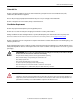
10. Lifetime Expectancy and MTBF
*) The Lifetime expectancy shown in the table indicates the minimum operating hours (service life) and is determined by the lifetime expectancy of the built-in electrolytic capacitors. Lifetime expectancy is
specified in operational hours and is calculated according to the capacitor’s manufacturer specification. The manufacturer of the electrolytic capacitors only guarantees a maximum life of up to 15 years (131 400h).
Any number exceeding this value is a calculated theoretical lifetime which can be used to compare devices.
**) MTBF stands for Mean Time Between Failure, which is calculated according to statistical device failures, and indicates reliability of a device. It is the statistical representation of the likelihood of a unit to fail and
does not necessarily represent the life of a product.
The MTBF figure is a statistical representation of the likelihood of a device to fail. A MTBF figure of e.g. 1 000 000h means that statistically one unit will fail every 100 hours if 10 000 units are installed in the field.
However, it can not be determined if the failed unit has been running for 50 000h or only for 100h.
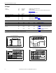
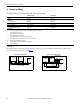
11. Functional Diagrams
AC 100V AC 120V AC 230V
Lifetime expectancy
*)
145 000h
*)
150 000h
*)
168 000h
*)
at 24V, 10A and 40°C
410 000h
*)
425 000h
*)
475 000h
*)
at 24V, 10A and 25°C
64 000h 70 000h 88 000h at 24V, 20A and 40°C
180 000h
*)
198 000h
*)
249 000h
*)
at 24V, 20A and 25°C
38 000h 46 000h 61 000h at 24V, 24A and 40°C
109 000h
*)
130 000h
*)
171 000h
*)
at 24V, 24A and 25°C
MTBF
**)
SN 29500, IEC 61709 468 000h 484 000h 537 000h
at 24V, 20A and 40°C
770 000h 796 000h 882 000h at 24V, 20A and 25°C
MTBF
**)
MIL HDBK 217F
254 000h 261 000h 290 000h at 24V, 20A and 40°C;
Ground Benign GB40
355 000h 361 000h 395 000h at 24V, 20A and 25°C;
Ground Benign GB25
56 000h 57 000h 64 000h at 24V, 20A and 40°C;
Ground Fixed GF40
75 000h 77 000h 86 000h at 24V, 20A and 25°C;
Ground Fixed GF25
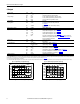
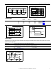
Fig. 11-1: Functional Diagram
+
+
-
-
Output
Over -
Vol t age
Protection
PFC
Converter
Output
Vol t age
Regulator
Pow er
Converter
Output
Filter
Output
Vol t age
Monitor
Output
Pow er
Manager
Temp er -
at ure
Shut-
down
Input Fuse
Input Filter
Input Rectifier
Active Inrush Limiter
V
OUT
L
N
DC-ok
Contact
DC-ok
LED
Single /
Parallel
DC-ok
Rel a y