
Reference Manual User guide
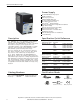
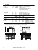
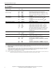
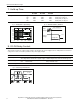
Table Of Contents
All parameters are specified at 48V, 10A, 230Vac, 25°C ambient and after a 5 minutes run-in time, unless noted otherwise.
10 Rockwell Automation Publication 1606-RM043A-EN-P — March 2014
Bulletin 1606 Switched Mode Power Supplies
10. Lifetime Expectancy and MTBF
AC 100V AC 120V AC 230V
Lifetime expectancy
*)
146 000h
*)
152 000h
*)
168 000h
*)
at 48V, 5A and 40°C
413 000h
*)
430 000h
*)
475 000h
*)
at 48V, 5A and 25°C
65 000h 70 000h 87 000h at 48V, 10A and 40°C
184 000h
*)
198 000h
*)
246 000h
*)
at 48V, 10A and 25°C
38 000h 43 000h 60 000h at 48V, 12A and 40°C
107 000h
*)
122 000h
*)
170 000h
*)
at 48V, 12A and 25°C
MTBF
**)
SN 29500, IEC 61709 468 000h 484 000h 537 000h at 48V, 10A and 40°C
770 000h 796 000h 882 000h at 48V, 10A and 25°C
MTBF
**)
MIL HDBK 217F 254 000h 261 000h 290 000h at 48V, 10A and 40°C;
Ground Benign GB40
355 000h 361 000h 395 000h at 48V, 10A and 25°C;
Ground Benign GB25
56 000h 57 000h 64 000h at 48V, 10A and 40°C;
Ground Fixed GF40
75 000h 77 000h 86 000h at 48V, 10A and 25°C;
Ground Fixed GF25
*) The Lifetime expectancy shown in the table indicates the minimum operating hours (service life) and is determined by the lifetime
expectancy of the built-in electrolytic capacitors. Lifetime expectancy is specied in operational hours and is calculated according to the
capacitor’s manufacturer specication. The manufacturer of the electrolytic capacitors only guarantees a maximum life of up to 15 years
(131 400h). Any number exceeding this value is a calculated theoretical lifetime which can be used to compare devices.
**) MTBF stands for Mean Time Between Failure, which is calculated according to statistical device failures, and indicates reliability of a
device. It is the statistical representation of the likelihood of a unit to fail and does not necessarily represent the life of a product.
The MTBF gure is a statistical representation of the likelihood of a device to fail. A MTBF gure of e.g. 1 000 000h means that
statistically one unit will fail every 100 hours if 10 000 units are installed in the eld. However, it cannot be determined if the failed unit
has been running for 50 000h or only for 100h.
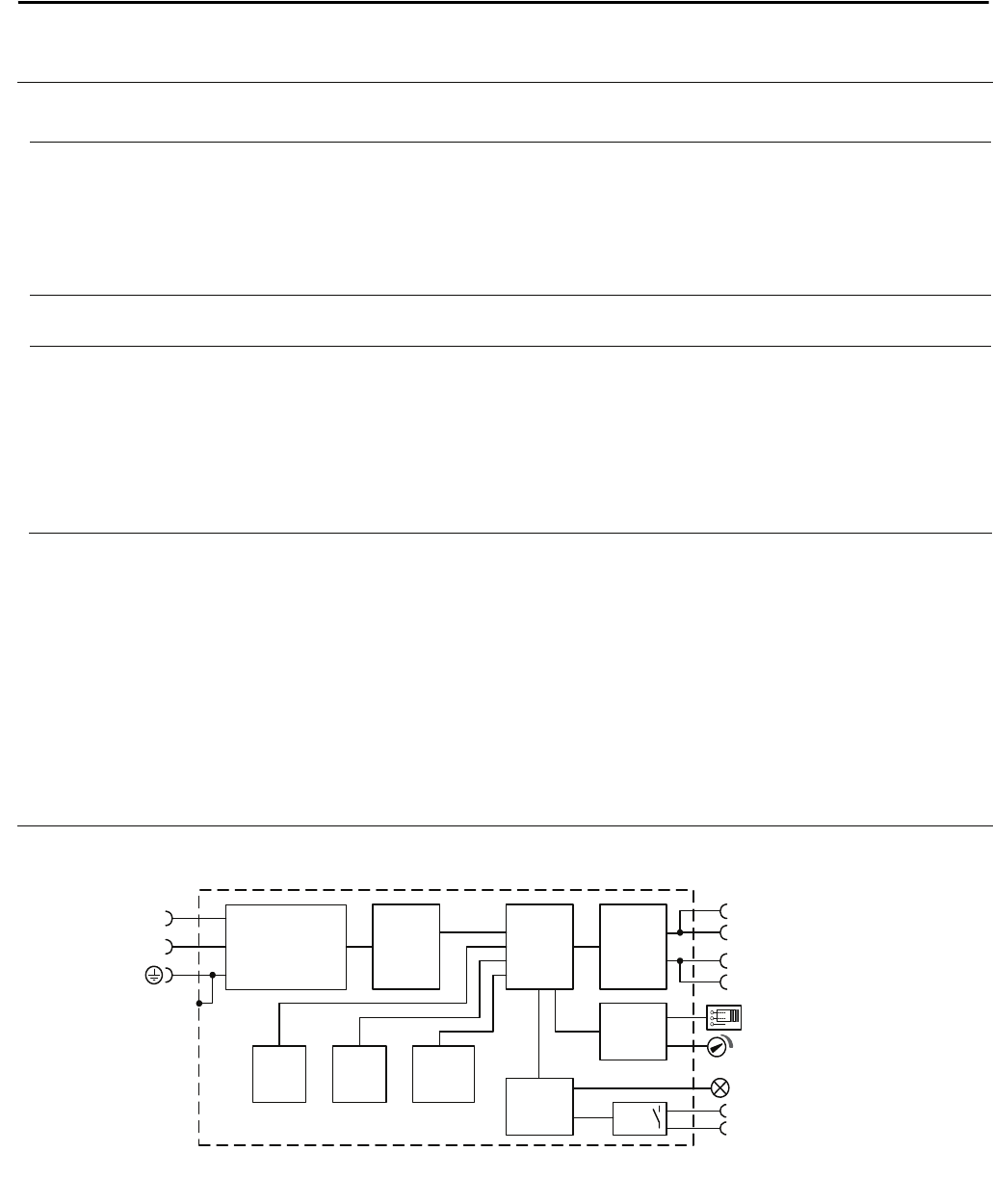
11. Functional Diagram
Fig. 11-1 Functional diagram
+
+
-
-
Output
Over-
Voltage
Protection
PFC
Converter
Output
Voltage
Regulator
Power
Converter
Output
Filter
Output
Voltage
Monitor
Output
Power
Manager
Temper-
ature
Shut-
down
Input Fuse
Input Filter
Input Rectier
Active Inrush Limiter
V
OUT
L
N
DC-ok
Contact
DC-ok
LED
Single /
Parallel
DC-ok
Relay