
Reference Manual User guide
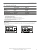
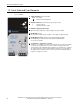
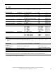
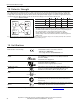
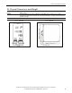
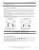
Table Of Contents
All parameters are specified at 48V, 10A, 230Vac, 25°C ambient and after a 5 minutes run-in time, unless noted otherwise.
12 Rockwell Automation Publication 1606-RM043A-EN-P — March 2014
Bulletin 1606 Switched Mode Power Supplies
13. Front Side and User Elements
Fig. 13-1 Front side
A
Input Terminals (screw terminals)
N, L Line input
PE (Protective Earth) input
B
Output Terminals (screw terminals, two pins per pole)
+ Positive output
– Negative (return) output
C
Output voltage potentiometer
Open the ap to adjust the output voltage. Factory set: 48.0V
D
DC-OK LED (green)
On, when the output voltage is >90% of the adjusted output voltage
E
DC-OK Relay Contact (quick-connect spring-clamp terminals)
The DC-OK relay contact is synchronized with the DC-OK LED.
See section for details.
F
“Parallel Use” “Single Use” selector
Set jumper to “Parallel Use” when power supplies are connected in parallel
to increase the output power. In order to achieve a sharing of the load
current between the individual power supplies, the “parallel use” regulates
the output voltage in such a manner that the voltage at no load is approx.
4% higher than at nominal load. See also section 24.5. A missing jumper is
equal to a “Single Use” mode.
C
D
E
F