
User Manual

Reference Manual
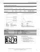
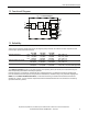
Bulletin 1606 Switched Mode Power Supplies
Catalog Number: 1606-XLP50E
Index
1. Description ........................................................1
2. Specication Quick Reference
............................1
3. Catalog Numbers ................................................1
4. Certication Marks..............................................1
5. AC-Input...............................................................4
6. Input Inrush Current Surge .................................5
7. DC-Input...............................................................5
8. Hold-up Time.......................................................6
9. DC-OK Output .....................................................6
10. Output .................................................................7
11. Efciency and Power Losses................................8
12. Functional Diagram.............................................9
13. Reliability .............................................................9
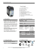
14. Front Side and User Elements...........................10
15. Terminals and Wiring........................................10
16. EMC....................................................................11
17. Environment ......................................................12
18. Protection Features ...........................................12
19. Safety .................................................................13
20. Dielectric Strength ............................................13
21. Certications .................................................... 14
22. Environmental Compliance ............................. 14
23. Physical Dimensions and Weight ..................... 15
24. Installation and Operation Instructions .......... 15
25. Accessory........................................................... 16
26. Application Notes............................................. 17
26.1. Peak Current Capability ......................... 17
26.2. Back-feeding Loads ................................ 17
26.3. Series Operation..................................... 18
26.4. Parallel Use to Increase Output Power . 18
26.5. Parallel Use for Redundancy.................. 18
26.6. Daisy Chaining of Outputs..................... 19
26.7. Charging Batteries ............................. 19
26.8. External Input Protection....................... 20
26.9. Inductive and Capacitive Loads ............. 20
26.10. Operation on Two Phases...................... 20
26.11. Use in a Tightly Sealed Enclosure .......... 20
26.12. Mounting Orientations.......................... 21
•PE and symbol—PE is the abbreviation for Protective Earth and has the same meaning as the symbol .
•Earth, Ground—This document uses the term “earth” which is the same as the U.S. term “ground”.
• T.b.d.—To be defined, value or description will follow later.
• AC 230V—A figure displayed with the AC or DC before the value represents a nominal voltage with standard tolerances (usually ±15%)
included. E.g.: DC 12V describes a 12V battery disregarding whether it is full (13.7V) or flat (10V)
• 230Vac—A figure with the unit (Vac) at the end is a momentary figure without any additional tolerances included.
• 50Hz vs. 60Hz—As long as not otherwise stated, AC100V and AC230V parameters are valid at 50Hz and AC120V parameters are valid at 60Hz
mains frequency.
•may—A key word indicating flexibility of choice with no implied preference.
•shall—A key word indicating a mandatory requirement.
•should—A key word indicating flexibility of choice
Terminology and Abbreviations