
User Manual

All parameters are specified at 24V, 2.1A, 230Vac input, 25ªC ambient and after a 5 minutes run-in time unless noted otherwise.
Rockwell Automation Publication 1606-RM034A-EN-P — March 2014 5
Bulletin 1606 Switched Mode Power Supplies
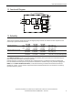
6. Input Inrush Current Surge
A NTC limits the input inrush current after turn-on of the input voltage. The inrush current is input voltage- and
ambient temperature-dependent.
AC 100V AC 120V AC 230V
Inrush current max. 18A
peak
23A
peak
48A
peak
40°C ambient, cold start
typ. 14A
peak
17A
peak
35A
peak
40°C ambient, cold start
Inrush energy
typ. 0.3A
2
s 0.4A
2
s 1.5A
2
s 40°C ambient, cold start
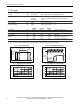
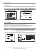
Fig. 6-1 Input inrush current, typical behavior Fig. 6-2 Input inrush current, zoom into the rst peak
Input: 230Vac
Output: 24V, 2.1A
Ambient: 40°C
Upper curve: Input current 20A / DIV
Middle curve: Input voltage 1000V / DIV
Lower curve: Output voltage 20V / DIV
Time scale: 20ms / DIV
Input: 30Vac
Output: 24V, 2.1A
Ambient: 40°C
Input current curve: 10A / DIV, 1ms / DIV
Ipeak 32.4A
The charging current into EMI suppression capacitors is
disregarded in the rst microseconds after switch-on.
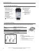
7. DC-Input
%03+/%52- V092-011 CD .mon tupni CD
noitarepo suounitnoC cdV573-58 .nim egnar tupni CD
A1.2 dna V42 ta cdV003 / cdV011 A91.0 / A05.0 .pyt tnerruc tupni CD
eulav etats ydaetS cdV18 .pyt egatlov no-nruT
Shut-down voltage typ. 58Vdc Steady state value
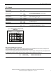
Fig. 7-1
Wiring for DC Input
Fuse
+
-
Load
L
N
PE
+
-
Power Supply
AC
DC
Battery
internal
fused
Instructions for DC use:
a) Use a battery or similar DC source.
b) Connect +pole to L and – pole to N.
c) Connect the PE terminal to a earth wire or
to the machine ground.
d) In case the – pole of the battery is not
connected to earth, use an appropriate fuse
to protect the N terminal.