
Reference Manual User guide
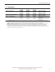

All parameters are specified at 48V, 5A, 230Vac, 25°C ambient and after a 5 minutes run-in time, unless noted otherwise.
12 Rockwell Automation Publication 1606-RM045A-EN-P — March 2014
Bulletin 1606 Switched Mode Power Supplies
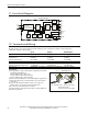
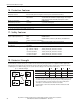
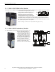
11. Functional Diagram
Fig. 11-1 Functional diagram
+
+
-
-
DC-ok
contact
Output
Over-
Voltage
Protection
PFC
Converter
Output
Voltage
Regulator
Power
Converter
Output
Filter
DC-ok
Relay
Output
Voltage
Monitor
Output
Power
Manager
Temper-
ature
Shut-
down
Overload
LED
DC-ok
LED
Input Fuse
Input Filter
Input Rectier
Active Transient Filter &
Inrush Current Limiter
V
OUT
L
N
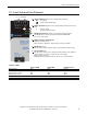
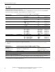
12. Terminals and Wiring
Bi-stable, quick-connect spring clamp terminals. IP20 Finger safe construction. Suitable for eld- and factory
installation. Shipped in open position.
Input Output DC-OK-Signal
Type
spring-clamp terminals spring-clamp terminals spring-clamp terminals
Solid wire 0.5-6mm
2
0.5-6mm
2
0.5-6mm
2
Stranded wire 0.5-4mm
2
0.5-4mm
2
0.5-4mm
2
American Wire Gauge 20-10 AWG 20-10 AWG 20-10 AWG
Wire stripping length 10mm / 0.4inch 10mm / 0.4inch 10mm / 0.4inch
Screwdriver not applicable not applicable not applicable
Recommended tightening torque not applicable not applicable not applicable
Pull-out force 10AWG:80N, 12AWG:60N, 14AWG:50N, 16AWG:40N (according to UL486E)
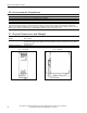
Fig. 12-1 Connecting a wire
Instructions:
a) Use appropriate copper cables that are designed for minimum
operating temperatures of:
60°C for ambient up to 45°C and
75°C for ambient up to 60°C minimum
90°C for ambient up to 70°C minimum.
b) Follow national installation codes and installation regulations!
c) Ensure that all strands of a stranded wire enter the terminal
connection!
d) Up to two stranded wires with the same cross section are
permitted in one connection point (except PE wire).
e) Do not use the unit without PE connection.
f) Unused terminal compartments should be securely tightened.
g) Ferrules are allowed.
1.
Insert the wire
2.
Close the lever
To disconnect wire:
reverse the above procedure.