
Reference Manual User guide

All parameters are specified at 48V, 5A, 230Vac, 25°C ambient and after a 5 minutes run-in time, unless noted otherwise.
Rockwell Automation Publication 1606-RM045A-EN-P — March 2014 13
Bulletin 1606 Switched Mode Power Supplies
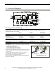
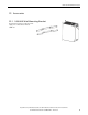
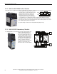
13. Front Side and User Elements
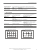
Fig. 13-1 Front side
A
Input Terminals (Quick-connect spring-clamp terminals)
N, L Line input
PE (Protective Earth) input
B
Output Terminals (Quick-connect spring-clamp terminals, two pins per
pole)
+ Positive output
– Negative (return) output
C
DC-OK Relay Contact (Quick-connect spring-clamp terminals)
The DC-OK relay contact is synchronized with the DC-OK LED.
See section 8 for details.
D
Output voltage potentiometer
Multi turn potentiometer;
Open the ap to adjust the output voltage. Factory set: 48.0V
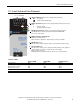
E
DC-OK LED (green)
On, when the output voltage is >90% of the adjusted output voltage
F
Overload LED (red)
On, when the voltage on the output terminals is <90% of the adjusted
output voltage, or in case of a short circuit in the output.
Input voltage is required
Flashing, when the unit has switched off due to over-temperature.
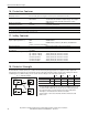
Indicators, LEDs
Overload LED DC-OK LED DC-OK Contact
Normal mode OFF ON Closed
During BonusPower OFF ON Closed
Overload (VOUT < 90%) ON OFF Open
Output short circuit ON OFF Open
Temperature Shut-down Intermitted OFF Open
No input power OFF OFF Open
A
B
C
D
E
F