
Reference Manual User guide

All parameters are specified at 48V, 5A, 230Vac, 25°C ambient and after a 5 minutes run-in time, unless noted otherwise.
Rockwell Automation Publication 1606-RM045A-EN-P — March 2014 27
Bulletin 1606 Switched Mode Power Supplies
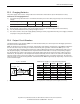
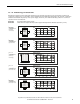
23.14. Mounting Orientations
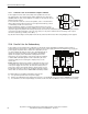
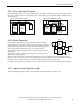
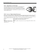
Mounting orientations other than input terminals on the bottom and output on the top require a reduction in
continuous output power or a limitation in the maximum allowed ambient temperature. The amount of reduction
inuences the lifetime expectancy of the power supply. Therefore, two different derating curves for continuous
operation can be found below:
Curve A1 Recommended output current.
Curve A2 Max allowed output current (results in approximately half the lifetime expectancy of A1).
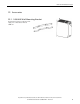
Fig. 23-8
Mounting
Orientation A
(Standard
orientation)
Power
Supply
OUTPUT
Output Current
0
10 20 30 40
60°C
2.5
5
7.5
10A
INPUT
50
A
1
Ambient Temperature
Fig. 23-9
Mounting
Orientation B
(Upside down)
Power
Supply
OUTPUT
INPUT
Output Current
0
10 20 30 40
60°C
2.5
5
7.5
10A
50
A
2
Ambient Temperature
A
1
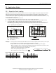
Fig. 23-10
Mounting
Orientation C
(Table-top
mounting)
Output Current
0
10 20 30 40
60°C
2.5
5
7.5
10A
50
Ambient Temperature
A
1
A
2
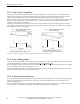
Fig. 23-11
Mounting
Orientation D
(Horizontal cw)
Power
Supply
OUTPUT
INPUT
Output Current
0
10 20 30 40
60°C
2.5
5
7.5
10A
50
Ambient Temperature
A
1
A
2
Fig. 23-12
Mounting
Orientation E
(Horizontal ccw)
Power
Supply
OUTPUT
INPUT
Output Current
0
10 20 30 40
60°C
2.5
5
7.5
10A
50
Ambient Temperature
A
1
A
2