
User Manual

12 DeviceNet 1732 ArmorBlock 16-Point I/O, Series A
Publication 1732D-IN002B-EN-E - January 2013
Configure Operations
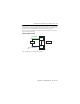
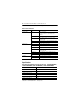
Auxiliary Power Cable
Refer to the pinout diagram to attach auxiliary power.
Mini-style 4-pin Male Connector
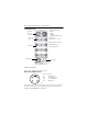
Input devices are powered from the DeviceNet power. Output devices are powered from
the module’s auxiliary power connector. Removing auxiliary power will deactivate all
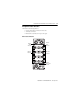
DeviceNet
Mini-style
Connectors
Node Address
Eight 12mm
I/O
Status LED
Auxiliary Power
All I/O Are 24V DC Sink In/
Source Out
- 16 Input
- 16 Output
- 16 Input Or Output Points Are
Any Mix of 16
(For Example, 15 + 1; 8 + 8)
Output Short Circuit Protected
Output Monitoring in
‘Self-configuring’ Style
43966
4
2
1
3
(view into connector)
Pin 1 Output Power+
Pin 2 Sensor/MDL Power+
Pin 3 Sensor/MDL Power-
Pin 4 Output Power-
43906