POINT I/O DeviceNet Adapter 1734-ADN, 1734-ADNX User Manual
Important User Information Because of the variety of uses for the products described in this publication, those responsible for the application and use of these products must satisfy themselves that all necessary steps have been taken to assure that each application and use meets all performance and safety requirements, including any applicable laws, regulations, codes and standards.
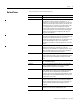
Summary of Changes Using Change Bars This document contains updated information. Changes are identified by change bars in the margin, as shown to the left. New and Revised Information The table below lists the new and revised information included in this release of the POINT I/O DeviceNet Adapter user manual. Table Summary of Changes.
Summary of Changes 2 Notes: Publication 1734-UM002C-EN-P - July 2003
Preface Purpose of this Manual This manual describes how to install, configure and operate your POINT I/O DeviceNet™ Adapter, catalog number 1734-ADN.
Preface 2 What the Manual Contains This manual contains the following sections: Chapter 1 - Installing the 1734-ADN(X) Adapter Chapter 2 - What is the 1734-ADN(X) Adapter? Description of how to install and wire the adapter Overview of the adapter’s features and functionality Module Status 63 DeviceNet Status DeviceBus Status 1734-ADN 1734-EP24DC System Power Field Power Chapter 3 - Using Auto Start Mode Or Description of how to use the Auto Start Mode on your adapter to quickly get your syste
Preface Related Terms 3 This manual uses the following terms: Term: Definition: Adapter POINT I/O DeviceNet adapter (1734-ADN and 1734-ADNX). Auto Catalog Replace The POINT I/O DeviceNet adapter supports the swapping of two identical modules connected to the adapter. I.e., if a 1734-IB4 is in slot 3 and another 1734-IB4 is in slot 7, the two modules can be removed from the POINT system and the slot 3 module placed into slot 7, and vice-versa.
Preface 4 Publication 1734-UM002C-EN-P - July 2003 Term: Definition: Cyclic DeviceNet communications method in which the adapter sends data cyclically based on a configured time value. Data is independently received cyclically from the sender. Data in both directions can be acknowledged or unacknowledged depending on the run time configuration of the system. MAC ID Media Access Control Identifier (DeviceNet network address). Master A DeviceNet network device (e.g.
Preface Related Products and Documentation Term: Definition: Subnet 1734-ADNX only. The Subnet DeviceNet Network, and is defined as the DeviceNet link that provides the expansion of the POINTBus to allow the 1734-ADNX to use its lower connector to add an additional 500 meters and up to 63 nodes which will be bridged through the 1734-ADNX up to the Primary Network. Note that backplane modules are also part of the Subnet.
Preface 6 • Do not leave spaces in the I/O. Instead, install all POINT I/O modules adjacent to each other. IMPORTANT If you must leave an I/O space open temporarily, you must change the keying position on the mounting base (1734-MB) to #5. This position will prevent you from installing the wrong I/O module on the base. • Populate every position on the DIN rail. • Do not add new I/O modules to the end of the POINT I/O system while the system is under power.
Table of Contents Chapter 1 Installing the 1734-ADN(X) Adapter Installing the Adapter . . . . . . . . . . . . . . . . . . . . . . Installing a Replacement DeviceNet Adapter in an Existing System . . . . . . . . . . . . . . . . . . . . . . . . . . . Wiring the Adapter . . . . . . . . . . . . . . . . . . . . . . . . DeviceNet Connection Plug Wiring and Subnet . Chapter Summary and What’s Next . . . . . . . . . . . . . . . . . . 1-2 . . . . . . . . . . . . . . . . . . . . . . . .
Table of Contents ii Chapter 4 Configuring the 1734-ADN(X) Adapter’s SubNet Configuration Overview . . . . . . . . . . . . . Adding the Scanner to Your Network . Adding I/O Modules to Your Network Setting the Scanner’s Parameters . . . . . Going Online. . . . . . . . . . . . . . . . . . . Chapter Summary and What’s Next . . . . . . . . . . . . . . . . . . . . . . . . . . . . . . . . . . . . . . . . . . . . . . . . . . . . . . . . . . . . . . . . . . . . . . . . . . . . . . . . . . .
Table of Contents 1734-OB2EP Protected Output Module . . . . . . . . . . 1734-OB4E Electronically Protected Output Module 1734-OV2E Protected Sink Output Module . . . . . . . 1734-OV4E Protected Sink Output Module . . . . . . . 1734-OW2 Relay Sink/Source Output Module . . . . . 1734-OX2 Relay Output Module . . . . . . . . . . . . . . . 1734-IE2C Analog Current Input Module . . . . . . . . . 1734-IE2V Analog Input Module . . . . . . . . . . . . . . . 1734-OE2C Analog Current Output Module. . . . . . .
Table of Contents iv Publication 1734-UM002C-EN-P - July 2003
Chapter 1 Installing the 1734-ADN(X) Adapter This chapter describes how to install and wire your adapter. For more information about: See page: Installing the Adapter 1-2 Installing a Replacement DeviceNet Adapter in an Existing System 1-4 Wiring the Adapter 1-5 Chapter Summary and What’s Next 1-6 When properly installed, POINT I/O is grounded through the DIN rail to chassis ground. We recommend using zinc plated, yellow chromated steel DIN rail to assure proper grounding.
1-2 Installing the 1734-ADN(X) Adapter Installing the Adapter To install the adapter on the DIN rail prior to installing other base units, proceed as follows. 1. Position the adapter vertically in front of the DIN rail. 2. Press firmly to install the adapter on the DIN rail. The locking mechanism locks the adapter to the DIN rail. DIN rail 1734-ADN(X) communication interface 31110-MC Orange screw slot 3. Insert the DeviceNet network plug and tighten the holding screws.
Installing the 1734-ADN(X) Adapter 1-3 4. Set the node address using the 2-position thumbwheel switch. Valid physical settings range from 00 to 63. Press either the + or - buttons to change the number. You can also set the node address to some value between 64-99. In this case, you can change the adapter’s node address via the RSNetWorx for DeviceNet software. If a value between 64-99 is used, at power-up the node address stored in the adapter’s non-volatile memory is used.
1-4 Installing the 1734-ADN(X) Adapter Installing a Replacement DeviceNet Adapter in an Existing System Your existing control application may be using another DeviceNet adapter (e.g., 1734-PDN) that you want to replace with a 1734-ADN(X) DeviceNet adapter. Remove the existing adapter from the DIN rail as follows: 1. Eliminate power to the adapter and all I/O modules in your existing system. 2. Remove the wiring assembly and DeviceNet cable from your existing adapter. 3. Remove the adjacent I/O module.
Installing the 1734-ADN(X) Adapter 1-5 6. Insert the new adapter into slot 0 using the steps described on page 1-2. 7. Reattach I/O modules to the new adapter. Wiring the Adapter Your adapter’s wiring and network designations are shown below.
1-6 Installing the 1734-ADN(X) Adapter Terminal Notes 0 No connection Reserved 1 No connection 2 Chassis Ground 3 Chassis Ground 4 Common 5 Common 6 Voltage Input 7 Voltage Input Apply 12/24V dc. Connects to the internal power bus.
Chapter 2 What is the 1734-ADN(X) Adapter? This chapter describes the POINT I/O DeviceNet adapter, including descriptions of the adapter’s features and functionality.
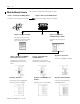
2-2 What is the 1734-ADN(X) Adapter? Using the Adapter The adapter resides on the primary DeviceNet network and the Subnet simultaneously. The PointBus maintains all DeviceNet network protocol but also offers configuration capabilities. IMPORTANT From this position, the adapter interfaces between DeviceNet devices and POINT I/O modules. The graphic below shows the adapter on the DeviceNet network and PointBus.
What is the 1734-ADN(X) Adapter? 2-3 Set Subnet/Backplane Baudrate The adapter and Subnet modules must use the same baudrate to communicate with each other. Use one or both of the following to set a Subnet baudrate. • Enable or disable the Backplane Autobaud feature for POINT I/O modules. POINT I/O modules have Autobaud enabled as the default- See page 2-12. • Set the adapter baudrate for the Subnet. The default for the 1734-ADN is 1Mbaud. The default for the 1734-ADNX is 125Kbaud - See page 2-9.
2-4 What is the 1734-ADN(X) Adapter? Configure the Subnet I/O In the first two steps, you set a consistent communication rate and made sure each module uses address for communication. Next you must configure the PointBus (e.g., set scan list). You can configure the PointBus using one of two methods: Auto Start Mode (ASM) or manually. For more information on configuring the PointBus using ASM, see Chapter 3 or see Chapter 4 for manual configuration.
What is the 1734-ADN(X) Adapter? 2-5 Remove and Reinsert Modules on the Backplane POINT I/O modules can easily be removed and reinserted on the 1734-ADN(X) backplane. If the removal and reinsertion is not done with caution, you can affect the adapter’s operations and, consequently, the entire POINT I/O application. If you must remove and reinsert modules, we recommend the following: • Do not move I/O modules to different locations on the DIN rail after they have been installed and configured.
2-6 What is the 1734-ADN(X) Adapter? – If modules of the same type are removed and returned to the wrong locations, the adapter identifies the returned modules, updates their MAC IDs and continues operation. IMPORTANT The removal and return scenario exists whether the system is under power or not. If the system is under power, the scenario arises immediately. If the system is not under power, the scenario arises in the next power cycle. Also, the example above shows removal of two adjacent modules.
What is the 1734-ADN(X) Adapter? 2-7 • Collects I/O data from the Subnet and sends it to devices on the DeviceNet network (e.g., scanners or controllers) • Supplies power to the backplane I/O modules (See Appendix A for power supply rules regarding I/O modules power requirements.) Data Collection The adapter collects I/O data from up to 63 modules via the Subnet. The I/O modules appear on the primary DeviceNet network as a single node, though, and require only one DeviceNet node address.
2-8 What is the 1734-ADN(X) Adapter? For more information on the 1734-EP24DC expansion power unit, see: • POINT I/O Technical Data, publication 1734-TD002 • POINT I/O 24V dc Expansion Power Supply Installation Instructions, publication 1734-IN058 Adapter Features Your adapter uses the following features on both the DeviceNet network and the PointBus: • • • • • Self-Test Field Upgradable Firmware Fully Software Configurable Connections Baudrates Self-Test On power-up, the adapter performs a self-test
What is the 1734-ADN(X) Adapter? 2-9 Connections Your adapter supports the following connections on both the primary DeviceNet network and Subnet: • I/O connections: – Polled – Strobe – Cyclic – COS • Explicit connections You can use I/O mapping to determine the data contained in each connection. The adapter supports Master/Slave connection types on the DeviceNet network. On the Subnet, the adapter functions as a scanner device, exchanging data with I/O modules.
2-10 What is the 1734-ADN(X) Adapter? Auto Catalog Replace Auto Catalog Replace corrects errors that might occur when backplane modules of the same type are removed and replaced in the wrong location. If modules of the same type are removed and returned to the wrong locations, the adapter identifies the returned modules, updates their MAC IDs and continues operation.
What is the 1734-ADN(X) Adapter? 2-11 Set this parameter in RSNetWorx for DeviceNet to one of the following baudrates: • • • • 125 Kbaud 250 Kbaud 500 Kbaud 1 Mbaud (available with the 1734-ADN only) When you download this parameter, the adapter sends a command to reset all present I/O modules on the backplane to the new baudrate. If additional modules are connected to the adapter, you must download the Backplane/Subnet Baudrate to make sure the new modules use the same rate as the others.
2-12 What is the 1734-ADN(X) Adapter? Backplane Autobaud The adapter itself never autobauds on the Subset. Backplane Autobaud automatically enables or disables Autobaud for all I/O modules currently attached to the backplane. The adapter does not set a specific rate, though (as with Backplane Baudrate). If you enable Backplane Autobaud in the adapter or the EDS parameter access that you set from the primary DeviceNet, the adapter only enables the Autobaud in all backplane I/O modules.
What is the 1734-ADN(X) Adapter? 2-13 Auto Address The EDS parameter Auto Address is available from the primary DeviceNet and lets the user sequentially order the node addresses of backplane I/O modules. This parameter is not a mode but occurs on a single occurrence only. The node address selected is assigned to the module closest to the adapter. The next closest module is assigned the next numerically higher value. The numbering pattern continues for all connected backplane I/O modules.
2-14 What is the 1734-ADN(X) Adapter? Cycling Node Status Using the Cycling Node Status parameter, you can easily determine the status of any POINT I/O modules with which the adapter is experiencing problems. A corresponding text string appears, including the MAC ID and a description of the status code reported in the Node Status Table. For more information on the Node Status Table, see page 2-23.
What is the 1734-ADN(X) Adapter? 2-15 Cycling I/O Mapping Cycling I/O Mapping is an EDS parameter accessible from the primary DeviceNet that shows you how data is mapped in the adapter’s scanlist. The data, as shown below, is listed in order of active modules in the scanlist.
2-16 What is the 1734-ADN(X) Adapter? The adapter is capable of holding approximately 64K of configuration data for POINT I/O modules connected to it. The adapter sends configuration data to an I/O module each time connections are created with that module (i.e., power cycle or module insertion to backplane). You can exchange an old module for a new one if the following conditions are met: • ADR is enabled for the adapter. • The new module matches the old one (i.e., electronic keying).
What is the 1734-ADN(X) Adapter? 2-17 Interscan Delay (ISD) Interscan Delay is the time delay between consecutive I/O scans of polled devices. The default setting is 10mS. The ISD=4ms for Auto Start mode. You can change this parameter in the RSNetWorx for DeviceNet software. The scanner uses this period of time to perform non-time-critical communications on the DeviceNet network, such as communicating with RSNetWorx for DeviceNet software.
2-18 What is the 1734-ADN(X) Adapter? Transmit Retries Transmit Retries are the maximum number of times that the scanner will attempt to send an I/O message to a device before it times out and generates an error message. You set this parameter in the RSNetWorx for DeviceNet software. IMPORTANT Communicating Through the Adapter We recommend that you do not change the Transmit Retries unless you are instructed to do so by a Rockwell Automation technical support representative.
What is the 1734-ADN(X) Adapter? 2-19 Overview of the Communication Process In a typical configuration, the adapter acts as an interface between a DeviceNet scanner (e.g., 1756-DNB) and POINT I/O modules. The example graphic below shows information transferred from a 1756-DNB to POINT I/O modules. IMPORTANT Although information is exchanged between the Logix5550 and 1756-DNB, this diagram (nor this chapter) is not designed to explain such an exchange.
2-20 What is the 1734-ADN(X) Adapter? Image Table Mapping Your adapter receives data from: • master devices (e.g., scanners) - output data is then passed to POINT I/O modules • input modules - input data is passed to the scanner The adapter must map the data it receives to its internal memory before passing it to the appropriate device.
What is the 1734-ADN(X) Adapter? 2-21 See Table 2.A for definitions of the first 2 bytes of each I/O message produced by the adapter on DeviceNet. Table 2.A I/O Status Word Bit Definitions Bit Byte 0 Byte 1 Operating Mode Operating Mode Description 0 0 = Run mode 1 = Idle mode Run - The adapter maps output data to each module on PointBus. 1 1 = Device failure (at least one device failed) Idle - Output data with zero length is sent to I/O modules.
2-22 What is the 1734-ADN(X) Adapter? Communicating with I/O Modules The adapter module supports multiple communication choices. These choices all use the default I/O structure previously described. The adapter’s master (e.g., 1756-DNB) makes the actual communication choice. The choices are: • Polled – Adapter sends data in response to received data. • Strobe – Adapter sends data in response to the strobe command. The single bit allocated to the adapter in the strobe message is not used.
What is the 1734-ADN(X) Adapter? Using Diagnostic Tables 2-23 The adapter maintains three diagnostic tables to manage the flow of data between a processor and a network’s devices. You can access the table over DeviceNet through the Scan Config Object (Class Code 0x90), Instance 1, via the following read-only attributes: • Faulted Node Table (Attribute 0xA) - In this 8-byte table, each bit represents a node on the backplane.
2-24 What is the 1734-ADN(X) Adapter? Table 2.B Node Status Table Numeric Code Definitions Numeric Code: Text Message: Definition: Take this action: 78 No Such Device Slave device in scan list table does not exist. Add the device to the network, or delete scan list entry for that device. 79 Transmit Failure Adapter has failed to transmit a message. Make sure that other modules exist on the backplane. 80 In Idle Mode Adapter is in IDLE mode. No action necessary.
Chapter 3 Using Auto Start Mode This chapter describes how to use the Auto Start Mode with your POINT I/O DeviceNet adapter.
3-2 Using Auto Start Mode Why Use Auto Start Mode? Auto Start Mode offers you a quick and easy method of getting your POINT I/O system ‘up and running’. If your POINT I/O application can use default configuration, you should use Auto Start Mode to easily begin operations. Once your adapter is: • installed • connected to the system’s I/O modules • online (in RSNetWorx for DeviceNet) you only need to choose the Auto Start Mode option and the adapter begins working with a default configuration.
Using Auto Start Mode 3-3 When the Adapter Uses Auto Start Mode, How Does it Map I/O Data? In Auto Start Mode, you can map I/O data in the adapter’s memory in one of the following ways: • • • • Byte Boundaries Word Boundaries Double Word Boundaries Fixed Boundaries Byte Boundaries Each node’s I/O data is mapped in the adapter’s memory at the next available byte. This option works best in applications that use Allen-Bradley PLCs and SLCs.
3-4 Using Auto Start Mode Are There Any Requirements to Using Auto Start Mode? There are two requirements to using the Auto Start Mode: • Your 1734-ADN DeviceNet adapter must use firmware revision 2.001 or higher. If your adapter does not have the required firmware, you can upgrade it with the ControlFlash tool. For more information on how to upgrade your adapter’s firmware, contact your Rockwell Automation representative.
Using Auto Start Mode 3-5 3. Insert the DeviceNet network plug and tighten the holding screws. DeviceNet network plug Holding screw 31111-MC Holding screw 4. Set the node address using the 2-position thumbwheel switch. Valid physical settings range from 00 to 63 (Factory setting =63). Press either the + or - buttons to change the number. You can also set the node address to some value between 64-99. In this case, you can change the adapter’s node address via the RSNetWorx for DeviceNet software.
3-6 Using Auto Start Mode 5. Slide the safety end cap up to remove it. This exposes the backplane and power interconnections. Safety end cap 31112-MC ATTENTION Publication 1734-UM002C-EN-P - July 2003 Do not discard the safety end cap. Use this end cap to cover the exposed interconnections on the last mounting base on the DIN rail. Failure to do so could result in equipment damage or injury from electric shock.
Using Auto Start Mode Wiring the Adapter 3-7 Your adapter’s wiring and network designations are shown below.
3-8 Using Auto Start Mode Terminal Notes 0 No connection Reserved 1 No connection 2 Chassis Ground 3 Chassis Ground 4 Common 5 Common 6 Voltage Input 7 Voltage Input Apply 12/24V dc. Connects to the internal power bus.
Using Auto Start Mode Adding Non-Backplane Modules to Subnet (1734-ADNX Only) 3-9 The Subnet must be properly terminated. A terminating resistor (included with the 1734-ADNX) must be placed at each end of the Subnet trunk segment (see the Rockwell Automation publication DeviceNet Cable System Planning and Installation Manual, publication no. DN-6.7.2). If no cable is attached to the 1734-ADNX Subnet connector, two resistors should be attached across the blue CAN_H and white CAN_L wires, as shown below.
3-10 Using Auto Start Mode Using RSNetWorx for DeviceNet You must use the RSNetWorx for DeviceNet software to configure your adapter. If using a 1734-ADNX adapter, make sure that you properly configure non-backplane modules for baudrate and MAC ID. Follow the steps below to use Auto Start Mode. 1. Go online in the software. IMPORTANT Auto Start Mode is only available when RSNetWorx for DeviceNet is online. A. Click on the Network pull-down menu. B. Choose Online. 2. Browse for the primary network (e.
Using Auto Start Mode 3-11 You can either: • upload configuration from the device to update the software • download configuration from the software to the device 4. Upload configuration from the device. Upload here. Beginning Auto Start Mode 1. After you upload configuration from the device to the software, you must begin Auto Start Mode. A. Click on the Parameters tab. B. Use the Auto Start Mode pull-down menu to choose a mapping option. The options are described on page 3-3. 2.
3-12 Using Auto Start Mode After 30-40 seconds, the adapter begins operations and uses the configuration most recently applied. During the auto start mode process, the Physical List Acquire Status field displays the words: Auto Start Mode, but after the download is complete the field displays the word: Idle.
Using Auto Start Mode 3-13 • An I/O module’s Network or Module/Network LED is solid red • It appears that the adapter has not saved a scanlist Use the following procedures to attempt to remedy the problem: • Verify that each non-backplane module’s address and baudrate have been set correctly. • Verify that each backplane module is configured to autobaud. The adapter’s EDS parameter “Set Backplane Autobaud’ can be used to set each module’s autobaud parameter.
3-14 Using Auto Start Mode Chapter Summary and What’s Next Publication 1734-UM002C-EN-P - July 2003 In this chapter, you learned about the Auto Start Mode. Move on to Chapter 4, Configuring the 1734-ADN(X) Adapter’s SubNet or to Chapter 5, Adding the 1734-ADN(X) to the DeviceNet Scanner’s Scanlist.
Chapter 4 Configuring the 1734-ADN(X) Adapter’s SubNet This chapter describes how to custom configure your adapter for use with POINT I/O modules. For more information about: See page: Configuration Overview 4-1 Adding the Scanner to Your Network 4-2 Adding I/O Modules to Your Network 4-3 Setting the Scanner’s Parameters 4-3 Going Online 4-8 Chapter Summary and What’s Next 4-8 Your adapter works on two networks simultaneously and must be configured for each separately.
4-2 Configuring the 1734-ADN(X) Adapter’s SubNet You must follow these steps during configuration: 1. Adding the Scanner to Your Network 2. Adding I/O Modules to Your Network 3. Setting the Scanner’s Parameters 4. Going Online Adding the Scanner to Your Network Follow these steps: 1. Start RSNetWorx for DeviceNet. 2. Add the scanner as shown below. 1. Expand the list of communication adapters. 2. Expand the 1734-ADN POINT I/O Scanner field. The scanner appears on the network.
Configuring the 1734-ADN(X) Adapter’s SubNet 4-3 Adding I/O Modules to Your Network After you add the scanner, you must add the modules connected to the scanner on the Subnet. In the offline mode, I/O modules must be added individually. Follow these steps: 1. Add modules as shown below. 1. Select the I/O module you want to add to the network. 2. Double-click on the catalog number to add the module. TIP: You can also click and drag the module name onto the network.
4-4 Configuring the 1734-ADN(X) Adapter’s SubNet You will see a pop-up screen with a series of tabs. Each tab provides options to write configuration for your adapter. The tabs are shown below and on the following pages. Type the scanner’s name here. Type a description here. The scanner’s address must = 0. This screen also shows the scanner’s device identity. These fields are read-only. At any point, you can click here to finish changing configuration parameters.
Configuring the 1734-ADN(X) Adapter’s SubNet 4-5 Set the Interscan Delay here. Set the Foreground to Background Poll Ratio here. Click here to reset the Interscan Delay and Foreground to Background Poll Ratio back to the module default values. Click here to change the Advanced Module Settings, as shown in the screen below. We recommend you DO NOT change module settings unless advised to do so by a Rockwell Automation support representative. Set the Expected Packet Rate here.
4-6 Configuring the 1734-ADN(X) Adapter’s SubNet Highlight a module and click here to unmap it. Click here to edit the advanced mapping parameters, as shown below. Click here to edit the automap options, as shown below. Use this pull-down menu to choose a Memory type. The Memory type corresponds to an I/O connections on DeviceNet. Set Map From parameters here. Click here when finished. Set the starting byte for I/O mapping. Choose a Data Alignment and click here. Set Map To parameters here.
Configuring the 1734-ADN(X) Adapter’s SubNet 4-7 The screens below show the remaining configuration tabs. Use this screen to choose Automatic Device Replacement options. You must have loaded each device into RSNetWorx for DeviceNet before loading using this button. You cannot change any configuration parameters on this screen. It is shown here to maintain the software’s graphical integrity. Click here when finished setting configuration parameters.
4-8 Configuring the 1734-ADN(X) Adapter’s SubNet Going Online After you set configuration parameters, your adapter must go online. Follow these steps: 1. Use the Network pull-down to go online. 1. Click on Network. 2. Click on Online. The software prompts you to save your configuration changes. 1. Click on Yes. 2. Choose your adapter’s network as shown below. 1. Select the DeviceNet interface. 2. Select the DeviceNet Network subnetwork.
Chapter 5 Adding the 1734-ADN(X) to the DeviceNet Scanner’s Scanlist This chapter describes how to custom configure your adapter for use with DeviceNet devices.
5-2 Adding the 1734-ADN(X) to the DeviceNet Scanner’s Scanlist You must follow these steps during configuration: 1. Adding the Adapter to Your Network 2. Setting the Adapter’s Parameters 3. Adding the DeviceNet scanner’s scanlist (see the Quick Start, Appendix B) 4. Going Online Adding the Adapter to Your Network Follow these steps: 1. Start the RSNetWorx for DeviceNet software. 2. Add the adapter as shown below. 1. Expand the list of communication adapters. 2.
Adding the 1734-ADN(X) to the DeviceNet Scanner’s Scanlist 5-3 Setting the Adapter’s Parameters After adding it to the network, you must configure the adapter for use with master DeviceNet devices. IMPORTANT This chapter shows configuration in the offline mode. Changes set in this mode do not take effect immediately. For configuration changes to take place, you must: • go online with your adapter • download the new configuration to your adapter For more information on how to go online, see page 5-6. 1.
5-4 Adding the 1734-ADN(X) to the DeviceNet Scanner’s Scanlist Use Associate File to associate this configuration file (i.e., configuring the 1734-ADN for communication with DeviceNet) with the configuration file that configures the same 1734-ADN for communication with POINT I/O modules. Use Clear Association to remove previously established configuration file associations that no longer apply to your adapter.
Adding the 1734-ADN(X) to the DeviceNet Scanner’s Scanlist 5-5 The screens below show the remaining configuration tabs. Connection sizes appear only when the Subnet network file has been associated using the Device Bridging tab. These values correspond to the 4 parameters (Poll/COS Connection Consume Size, Poll Connection Produce Size, COS Connection Produce Size, Strobe Connection Produce Size) found on the Device Parameter’s tab. Click here to view the EDS file.
5-6 Adding the 1734-ADN(X) to the DeviceNet Scanner’s Scanlist Going Online Follow these steps for the adapter to go online: 1. Use the Network pull-down. 1. Click on Network. 2. Click on Online. The software prompts you to save your configuration changes. 1. Click on Yes. 2. Choose your adapter’s network as shown below. 1. Select the DeviceNet interface. 2. Select the DeviceNet Network subnetwork. This selection accesses the Subnet to configure the adapter on the DeviceNet network. 3. Click here.
Chapter 6 Troubleshooting the 1734-ADN(X) Adapter This chapter describes how to troubleshoot your adapter. To learn how to: Use the Status Indicators See page: Use the Status Indicators 6-1 Use Guidelines for Using Your Adapter 6-4 Chapter Summary and What’s Next 6-4 You can use the status indicators to troubleshoot your adapter. The graphic below shows the adapter’s status indicators.
6-2 Troubleshooting the 1734-ADN(X) Adapter Use the table below to troubleshoot your adapter. Indicator: Indication: Probable Cause: System Power Off Any of the following: 1. Not active 2. Field power is OFF 3. DC-DC converter problem Field Power Adapter Status Publication 1734-UM002C-EN-P - July 2003 Green Any of the following: 1. System power ON 2. DC-DC converter active (5V) Off Any of the following: 1. Not active 2. Field power is OFF Take This Action: 1. Check adapter configuration 2.
Troubleshooting the 1734-ADN(X) Adapter 6-3 Indicator: Indication: Probable Cause: Take This Action: Network Status Off Device is not online - Device is autobauding - Device has not completed dup_MAC_id test - Device not powered Check adapter status indicator to determine if more time is needed to complete the dup_MAC_id test or if the adapter needs to be powered Flashing Green Device is on-line but has no None connections in the established state Green Device on-line and has connections in the
6-4 Troubleshooting the 1734-ADN(X) Adapter Guidelines for Using Your Adapter Remember the following operational guidelines when using your 1734-ADN(X) adapter. • Do not leave spaces in the I/O. Instead, install all POINT I/O modules adjacent to each other. IMPORTANT If you must leave an I/O space open temporarily, make sure you change the keying position on the mounting base (1734-MB) to #5. This position will prevent you from installing the wrong I/O module on the base.
Appendix A Specifications Specifications - 1734-ADN(X) DeviceNet Adapter Module Communication Interface Specifications Expansion I/O Capacity Up to 13 modules (13 times 75mA = 0.975, just under the limit of 1.0A). The actual number of modules can vary. Add up the current requirements of the modules you want to use to make sure they do not exceed the amperage limit of the 1734-ADN.
A-2 Specifications DeviceNet Power Specifications Power Supply Note: In order to comply with CE Low Voltage Directives (LVD), you must use a Safety Extra Low Voltage (SELV) or a Protected Extra Low Voltage (PELV) power supply to power this adapter.
Specifications Dimensions Inches (Millimeters) Environmental Conditions Operational Temperature Storage Temperature Relative Humidity ShockOperating Non-operating Vibration 3.0H x 2.16W x 5.25L (76.2H x 54.9W x 133.4L) Conductors Wire Size 14 AWG (2.5mm2) - 22 AWG (0.25mm2) solid or stranded maximum 3/64 inch (1.2mm) insulation maximum 21 5-7 pound-inches (0.5-0.
A-4 Specifications Notes: Publication 1734-UM002C-EN-P - July 2003
Appendix B 1734-ADNX Quick Start What’s In This Appendix? In this Quick Start, you will learn how to use the 1734-ADNX with a ControlLogix system on DeviceNet. You will also use one of the 1734-ADNX’s features (Auto Start Mode) in an exercise to automatically configure devices on its Subnet. When you complete this quick start you will be familiar with: • The 1734-ADNX as an adapter on the ControlLogix primary DeviceNet network and as a scanner on the DeviceNet expansion Subnet.
B-2 1734-ADNX Quick Start The new Subnet system attributes include: • Most field devices are more than 100m from the ControlLogix Processor • Previously installed and documented at 500 Kbaud • 1734-ADNX with discrete inputs and outputs for several field devices • DeviceNet Starter Auxiliary (DSA) • DeviceNet RightSight Photoelectric Sensor • The ability to be replicated several times in the future without changing documentation. (i.e., devices will be replicated with same attributes, node addresses, etc.
1734-ADNX Quick Start B-3 3. Select DeviceNet configuration. 4. Click OK. Now that you have created a new DeviceNet project, go online by selecting the Online icon on the toolbar. 5. A list of the available drivers in RSLinx appears. Drill down from Ethernet into your ControlLogix project through the backplane to your 1756-DNB in slot 8. Select channel A, as shown below. Your system may not be configured as illustrated.
B-4 1734-ADNX Quick Start RSNetWorx will go online. A screen similar to the one below will appear: 8. After the browse is complete, from the RSNetWorx for DeviceNet main menu select File>Save As. 9. Type in MainNetwork (use this exact name to avoid confusion later) as the filename. 10. Click Save. You see a screen similar to the following:. Your system may not look like the above system. (You may have more or less nodes.
1734-ADNX Quick Start B-5 c. Select the scanlist tab and when prompted click Download. 12. When the download is complete, add the 1734-ADNX to the scanlist by selecting the 1734-ADNX (node 16) and clicking the single right arrow. A warning window opens that says that the 1734-ADNX does not contain any I/O data. At this point, RSNetWorx for DeviceNet does not know how many bytes of data are being inputted and outputted to the Subnet so it cannot fill in the values for you. 13.
B-6 1734-ADNX Quick Start 15. Click Edit I/O Parameters. Click the 1734-ADNX in the Scanlist and then click Edit I/O Parameters to verify input and output bytes. 16. Verify that nothing is filled in for input and output sizes (both are zero). If you knew how much data was being produced and consumed on the Subnet, you could fill these fields in manually. Because it is easier to let RSNetWorx for DeviceNet fill in these values for us, Click Cancel to close this window.
1734-ADNX Quick Start B-7 17. Remove the 1734-ADNX from the scanlist for now by clicking the double arrows. Click the double left arrow to remove the 1734-ADNX from the Scanlist. Then verify that the Scanlist is empty. You will return here later after RSNetWorx for DeviceNet knows more about the devices on the Subnet. 18. Click OK. When prompted if you want to download changes to the device, click Yes.
B-8 1734-ADNX Quick Start If you are not going to use the subnet, you must still terminate it! You can use the connector provided with the 1734-ADNX and connect two resistors between the white and blue positions. 20475w-res • Termination resistors are 121 Ohms, 1/4 Watt, 1%, Rockwell part number 1785A-C2. • Do not use carbon resistors. Metal film is recommended. Continue ONLY after You have verified that the taps are terminated correctly. 20. Double click on the 1734-ADNX to open the properties window.
1734-ADNX Quick Start B-9 22. Verify that your screen looks similiar to the following screen: Review of the 1734-ADNX Rules and the MAC ID Parameter To understand some of the MAC ID parameters, you should review some of the rules for using the 1734-ADNX. • The 1734-ADNX always has address 0 on the Subnet. • All POINT I/O backplane module MAC IDs must be numerically less than those of non-backplane Subnet modules (for our example, the POINT I/O node numbers must be less than the DSA and photoswitch).
B-10 1734-ADNX Quick Start • A unique attribute, Max(imum) Backplane MACID has been added to 1734-ADNX. This value represents the highest node address of a module residing on the backplane. This value must be greater than or equal to the rightmost backplane POINT I/O module, but must be less than that of any non-backplane Subnet module. You select this value to allow for the future addition of backplane modules.
1734-ADNX Quick Start B-11 When the adapter completes this sequence of events, the POINT I/O modules connected to the adapter are ready to accept connections from a scanner. IMPORTANT Although Auto Start Mode lets your adapter (1734-ADNX) operate with a default configuration, you can choose to manually change the configuration after operation has begun or you can write a custom configuration.
B-12 1734-ADNX Quick Start A window describing Auto Start Mode opens. Right now, the 1734-ADNX is not in another scanner’s scanlist so you can use the Auto Start Mode feature. By using Auto Start Mode, the 1734-ADNX will map all the devices on the Subnet and automatically adjust the value for parameters 1, 9, 10, 11, and 12. 2. Select the dropdown box next to parameter 6. You can map the data using the four options discussed earlier.
1734-ADNX Quick Start B-13 Notice that parameters 9, 10, 11 and 12 are still at their default of 2 bytes. These values will be filled out for you when this action is complete. Download parameters to the device Monitor icon 4. Make sure All is selected then click the icon to download parameters to the device (this triggers the Auto Start Mode). 5. Click the Monitor icon and notice: • Parameter 6 has gone back to "Do Nothing".
B-14 1734-ADNX Quick Start • Parameter 3: Verify the Backplane Baudrate is 500 Kbaud. If it is not, you will need to find out why and make the necessary corrections. • Parameter 9, 10 11 and 12 have been filled in for you. Expand the column to view all the text. Consume size is data that the adapter will consume from the scanner. These are the outputs being sent from the scanner to the POINT I/O adapter. Produce size is data the 1734-ADNX adapter will produce for the 1756-DNB scanner.
1734-ADNX Quick Start B-15 Browse the Subnet Look at the Subnet at this point to make things more clear. 1. From the RSNetWorx for DeviceNet main menu, select File>New and then select DeviceNet Configuration. 2. Click OK. Now that you have a new DeviceNet project created. 3. Click the Online icon. Last time you browsed to the 1756-DNB. This time you will browse a little deeper. 4.
B-16 1734-ADNX Quick Start 6. From the RSNetWorx for DeviceNet main menu, select File>Save As. 7. Type in SubNet as the filename. 8. Click Save. IMPORTANT You must save your work before continuing. 9. Verify your screen appears as shown below. The nodes can be in any order. Verify: • All five are there • They have the correct node numbers On the Subnet, the 1734-ADNX is a scanner and it is always at node 0.
1734-ADNX Quick Start B-17 Make sure you click Upload! You do not want to download over the configuration you just created. 12. When the upload is complete, select the scanlist tab. • Verify your scanlist matches that shown below. • Notice that all the POINT I/O, the DSA, and the RightSight have been added to the scanlist as you probably expected. You are about to look at the input and output tabs. Based on your selections earlier, all the data should be mapped to word boundaries.
B-18 1734-ADNX Quick Start Inputs and Outputs 1. Select the Input tab. A single word is 16 bits. Notice that the mapping is as expected. • The first two bytes (1 byte = 8 bits) are reserved as read only. • The first word is completely used, so the 1734-IB4 can map to the beginning of the next word (Byte 2, bit 0). • There is a space between the 1734-IB4 and the 1734-OB4E because the next word does not start until Byte 4. The same is true for the DSA and the RightSight.
1734-ADNX Quick Start B-19 This matches what you observed earlier on the main network: Earlier view of the parameters. The primary network knew you were producing 9 bytes of data. • The data mapped in the 1734-ADNX will be exchanged with the 1756-DNB scanner. • There are three memory buffers that the 1734-ADNX uses for input data to the scanner on DeviceNet. The buffers are Cos/Cyclic, Polled, and Strobed. You can map data into any of the three buffer areas on the adapter.
B-20 1734-ADNX Quick Start Note that for the 1734-ADNX, each line in the mapping area represents a byte of data. When you view the 1756-DNB, each line will be 4 bytes of data (double word). Now you are ready to take a look at the output side. Based on the numbers you saw on the main network you expect to see 5 bytes (two of them are going to be reserved status words). Earlier view of the parameters.
1734-ADNX Quick Start B-21 You should still be looking at the subnet 1734-ADNX Input tab. Now select the Output tab and verify you have the following: • Notice the RightSight does not appear. • It is an input to the scanner - reporting if an object is detected. • It does not have any outputs. • The DSA has both inputs and outputs. These two say read only, but since it is an output tab, a better description is “reserved for future use”. 5. Expand the plus next to node 2.
B-22 1734-ADNX Quick Start 6. Select Output Value #1 and notice the exact location of that bit is displayed. You can easily tell that Output Value #1 is in Byte 2, Bit 1. This information will make it very easy to write your ladder logic later. You uploaded the scanlist and looked at the Input and Output data. Now you are about to save this information to your hard disk. 7. Click OK (not cancel) to close this window. Click OK and not Cancel to close the window.
1734-ADNX Quick Start 8. B-23 From the RSNetWorx for DeviceNet main menu, select File>Save. IMPORTANT You must save your work before moving on. Now all the information is saved in the file Subnet.dnt. Navigate Between Networks A nice feature of RSNetWorx for DeviceNet is the easy way it lets you commission the Subnet. You can have two DeviceNet projects because there are actually two DeviceNet networks.
B-24 1734-ADNX Quick Start 2. Select the Device Bridging tab. The following window opens. This window lets you define a file that is “associated” with this one through the 1734-ADNX. Once you specify the associated file, you will be able to jump to that file through a menu selection from the 1734-ADNX. The file you need to associate in this case is the MainNetwork.dnt project file you created earlier. 3. Click the Associate File button. 4.
1734-ADNX Quick Start 7. B-25 From the RSNetWorx for DeviceNet main menu, select File>Save. Now you can observe how you would switch networks. Switch Between Networks 1. Move the cursor over the 1734-ADNX in the network browse window:. 2. Press the right mouse button. 3. Click Associated Network from the menu. If prompted to save your changes, you must select Yes (you will probably not get this prompt if you saved earlier). To get back to the main network, associate the Subnet.
B-26 1734-ADNX Quick Start 6. Click Associate File to associate the Subnet.dnt file to the main network. 7. Press OK (not cancel) to save the association. Now that they are associated, you can easily jump between the main network and the subnet and vice versa. Another advantage is that the main network has access to the information saved in Subnet.dnt. 8. Click the Online icon. 9. When prompted to save, click Yes. 10. At the prompt, click OK. 11.
1734-ADNX Quick Start B-27 13. Change the slot number to 8 (see illustration below) so it matches the 1756-DNBs location in the 1756-Rack. Then click the Scanlist tab. Scanlist tab Slot Number 14. Select nodes 1, 15, 16 and 20, then use the single right arrow to add them to your scanlist. • Notice that you did not get the error message that you received earlier, when you were told that the 1734-ADNX POINT I/O DeviceNet Adapter does not contain any I/O data.
B-28 1734-ADNX Quick Start You might have more nodes on your DeviceNet Network, but only add 1, 15, 16 and 20 to the scanlist as shown here. Click to add available devices to scanlist. Click to download to the scanner. Edit I/O Parameters button. 15. Select only the 1734-ADNX (node 16) then click Edit I/O Parameters. Notice the fields have been filled in for you. The values match what was observed earlier. Values observed earlier.
1734-ADNX Quick Start B-29 • The 1756-DNB scanner will be receiving 9 bytes of data that the 1734-ADNX produces such as the state of the RightSight. • The 1756-DNB scanner will be outputting 5 bytes of data that the 1734-ADNX consumes such as the 1734-OB4E outputs. Sometimes it is easy to get confused and reverse the numbers if these values are entered manually (in this case, entering incorrectly input size = 5 and output size = 9).
B-30 1734-ADNX Quick Start You associated the files, so scroll down until you see the RightSight at node 22 on the subnet. 18. Select the RightSight. Notice that its data is at 8:I.Data[3].8 (it starts at bit 8). You will need that address for our RSLogix5000 program. 19. Now select the Output tab and find the bit for Output Value #1 on the 1734-OB4E. It should be 8:O.Data[0].25 as shown below.
1734-ADNX Quick Start B-31 You are now ready to write your RSLogix5000 program. 20. Click Apply. 21. Click Yes when prompted to download these changes to the device. 22. Click OK to close the 1756-DNB Output tab. 23. Exit RSNetWorx for DeviceNet. This is not a necessary step, but it will show you that RSLogix5000 can launch RSNetWorx for DeviceNet 24. When prompted to save, Click Yes. You have completed the 1734-ADNX Quick Start.
B-32 1734-ADNX Quick Start Notes: Publication 1734-UM002C-EN-P - July 2003
Appendix C 1734-ADNX Rules and Guidelines Regarding How to Use the 1734-ADNX RULE 1: A DeviceNet Subnet may not bridge directly to another DeviceNet Subnet. A 1734-ADNX may not be used on the Subnet of another 1734-ADNX. NOTE: The 1734-ADNX will fault and report an error with any attempt to route message beyond the Subnet.
C-2 1734-ADNX Rules and Guidelines Regarding How to Use the 1734-ADNX RULE 7: The EDS parameter, “Max Backplane MACID” must be set to not be lower than that of any backplane modules. If no backplane modules are used, this value can be set to be 0, allowing modules 1-63 to be attached to the Subnet using DeviceNet cable. RULE 8: Backplane modules are always addressed in increasing order from left to right. Gaps in the backplane addressing are permitted. Empty slots in the backplane are NOT permitted.
Appendix D Default Data Maps I/O messages are sent to (consumed) and received from (produced) the POINT I/O modules. These messages are mapped into the processor’s memory. This appendix lists the default data maps for 1734 POINT I/O and 1734-POINTBlock modules.
D-2 Default Data Maps 1734-IA2 Input Module Message size: 1 Byte 7 6 5 4 3 2 Produces (scanner Rx) Consumes (scanner Tx) 1 0 Ch1 Ch0 1 0 Ch1 Ch0 No consumed data Where: Ch0 = channel 0, Ch1 = channel 1; 0 = off, 1 = on 1734-IB2 Sink Input Module Message size: 1 Byte 7 6 5 4 3 2 Produces (scanner Rx) Consumes (scanner Tx) No consumed data Where: Ch0 = channel 0, Ch1 = channel 1; 0 = OFF 1 = ON 1734-IB4 Sink Input Module Message size: 1 Byte 7 6 5 Produces (scanner Rx) Consumes
Default Data Maps D-3 1734-IV2 Source Input Module Message size: 1 Byte 7 6 5 4 3 2 Produces (scanner Rx) Consumes (scanner Tx) 1 0 Ch1 Ch0 No consumed data Where: Ch0 = input channel 0 data Ch1 = input channel 1 data 1734-IV4 Source Input Module Message size: 1 Byte 7 6 5 4 Produces (scanner Rx) Consumes (scanner Tx) 3 2 1 0 Ch3 Ch1 Ch1 Ch0 No consumed data Where: Ch0 = input channel 0 Ch1 = input channel 1 Ch2 = input channel 2 Ch3 = input channel 3 1734-OA2 Output Module Mes
D-4 Default Data Maps 1734-OB2E Electronically Protected Output Module Message size: 1 Byte 7 6 5 Produces (scanner Rx) 4 3 2 Not used 1 0 Ch1 Ch0 1 0 Ch1 Ch0 Channel status Where: 0 = no error 1 = error Message size: 1 Byte 7 6 5 Consumes (scanner Tx) 4 3 2 Not used Channel state Where: 0 = OFF 1 = ON 1734-OB2EP Protected Output Module Message size: 1 Byte 7 6 5 Produces (scanner Rx) 4 3 2 Not used 1 0 Ch1 Ch0 1 0 Ch1 Ch0 Channel status Where: 0 = no error 1 =
Default Data Maps D-5 Message size: 1 Byte 7 6 Consumes (scanner Tx) 5 4 Not used 3 2 1 0 Ch3 Ch2 Ch1 Ch0 Channel state Where: 0 = Off 1 = On 1734-OV2E Protected Sink Output Module Message size: 1 Byte 7 Produces (scanner Rx) 6 5 4 3 2 Not used 1 0 Ch1 Ch0 1 0 Ch1 Ch0 Channel status Where: 0 = no error 1 = error Message size: 1 Byte 7 Consumes (scanner Tx) 6 5 4 3 2 Not used Channel state Where: 0 = OFF 1 = ON 1734-OV4E Protected Sink Output Module Message size: 1
D-6 Default Data Maps 1734-OW2 Relay Sink/Source Output Module Message size: 1 Byte 7 6 5 4 Consumes (scanner Tx) 3 2 Not used 1 0 Ch1 Ch0 1 0 Ch1 Ch0 Channel state Where: 0 = OFF 1 = ON 1734-OX2 Relay Output Module Message size: 1 Byte 7 6 5 4 Consumes (scanner Tx) 3 2 Not used Channel state Where: 0 = NO contact OFF, NC contact ON1 = NO contact ON, NC contact OFF 1734-IE2C Analog Current Input Module Message size: 6 Bytes 15 Produces (scanner Rx) 14 13 12 11 10 09 08
D-7 Default Data Maps Channel Status Table D.
D-8 Default Data Maps 1734-OE2C Analog Current Output Module Message size: 4 bytes 15 14 Consumes (Tx) 13 12 11 10 09 08 07 06 05 04 03 02 Output Channel 0 High Byte Output Channel 0 Low Byte Output Channel 1 High Byte Output Channel 1 Low Byte 01 00 01 00 CM CF Message size: 2 Bytes 15 14 Produces (Rx) 13 12 11 10 09 08 07 06 High Byte - Channel 1 Status Not used HCA LCA 05 04 03 02 Low Byte - Channel 0 Status CM CF Not used HCA LCA Where:CF = Channel Fault
D-9 Default Data Maps 1734-IJ Encoder/Counter Module Message size: 6 Bytes 15 14 13 12 11 10 09 08 07 06 05 04 03 02 01 00 0 0 ZS BS AS C1 C0 ZD 0 Produces (scanner Rx) Channel 0 value of present counter state (LSW) Channel 0 value of present counter state (MSW) PE EF NR 0 0 0 0 Where: PE = Programming error EF = EEPROM fault status NR = Not ready status bit ZS = Z input status BS = B input status AS = A input status C = Stored data count ZD = Zero frequency detected LSW =
D-10 Default Data Maps 1734-IM2 Input Module Message size: 1 Byte 7 6 5 4 3 2 Produces (Rx) Consumes (Tx) 1 0 Ch1 Ch0 No consumed data Where: Ch0 = channel 0, ICh1 = channel 1; 0 = off, 1 = on 1734-IR2 RTD Input Module Message size: 6 Bytes 15 14 13 12 11 10 09 08 07 06 05 04 Produces (scanner Rx) Input Channel 0 - High Byte Input Channel 0 - Low Byte Input Channel 1 - High Byte Input Channel 1 - Low Byte Status Byte for Channel 1 Status Byte for Channel 0 OR Consumes (scann
D-11 Default Data Maps 1734-IT2I Isolated Thermocouple Input Module Message size: 8 Bytes 15 14 13 12 11 10 09 08 07 06 05 04 Produces (scanner Rx) Input Channel 0 - High Byte Input Channel 0 - Low Byte Input Channel 1 - High Byte Input Channel 1 - Low Byte Status Byte for Channel 1 Status Byte for Channel 0 Consumes (scanner Tx) OR UR HHA L LA HA LA CM CF OR UR HHA L LA OR UR Cold Junction Temperature (Selectable: Channel 0, Channel 1, or Average of both Channel 0 and 1) 0
D-12 Default Data Maps 1734-VHSC 5V dc High Speed Counter Module Message size: 6 Bytes 15 14 13 12 11 10 09 08 07 06 05 04 03 02 01 00 OS 0 ZS BS AS C1 C0 ZD 0 Produces (scanner Rx) Channel 0 value of present counter state (LSW) Channel 0 value of present counter state (MSW) PE EF NR 0 FS FS OS Where: PE = Programming error EF = EEPROM fault status NR = Not ready status bit FS = Output fault status bit - bit 10 for output 0, bit 11 for output 1 OS = Output on/off status bit
Default Data Maps D-13 1734-232ASC ASCII Module Default Receive Data Assembly Format (Default Mode) Byte 1 Byte 2 Rx Transaction ID Byte Status Byte Byte 3 Reserved Byte 4 Length Byte 5-23 ASCII Data Byte 24 (Terminator) Default Transmit Data Assembly Format (Default Mode) Byte 1 Reserved Byte 2 TX Transaction ID Byte Byte 3 Reserved Byte 4 Length Byte 5-23 ASCII Data Byte 24 (Terminator) Publication 1734-UM002C-EN-P - July 2003
D-14 Default Data Maps Publication 1734-UM002C-EN-P - July 2003
Index Numbers 1734-232ASC data map D-13 1734-ADNX guidelines on how to use C-1 rules on how to use C-1 1734-ADNX MAC ID parameters rules B-9 1734-ADNX quick start review auto start mode B-11 assumptions B-1 browse the subnet B-15 inputs and outputs B-18 navigate between networks B-23 review 1734-ADNX MAC ID parameters B-9 review 1734-ADNX rules B-9 switch between networks B-25 1734-ADNX rules review D-9 1734-IA2 data map D-2 1734-IB2 data map D-2 1734-IB4 data map D-2 1734-IE2C data map D-6 1734-IE2V data
2 Index communicating with I/O modules 2-22 image table mapping 2-20 mapping data 2-18 overview of the process 2-19 configuration adding I/O modules to your network 4-3 adding the adapter to your network 4-2 adding the scanner to your network 4-2 configuring the adapter for DeviceNet 4-1 configuring the adapter for PointBus 2-4 going online 4-8, 5-6 RSNetWorx for DeviceNet 1-3, Preface-4 setting the adapter’s parameters 4-3 setting the scanner’s parameters 4-3 using EDS files 4-5 connections to and from
Index I 3 Q I/O status word bit 2-21 idle node table 2-23 image table mapping 2-20 important user information 2 inputs and outputs tab 2-18 installing I/O modules 3-8 installing the adapter 1-1, 1-4 interscan delay 2-17 setting in RSNetWorx for DeviceNet 4-5 M quick start 1734-ADNX B-1 R related documentation Preface-5 related products Preface-5 remove and reinsert modules on DeviceNet network 2-5 replacing an Existing Adapter 1-4 review 1734-ADNX MAC ID parameters B-9 map from parameters setting i
4 Index troubleshooting using status indicators 6-1 U updating adapter firmware using the ControlFlash utility Preface-3 using diagnostic tables 2-23 Publication 1734-UM002C-EN-P - July 2003 using the adatper guidelines Preface-5 W who should use manual Preface-1 wiring the adapter 3-7
How Are We Doing? Your comments on our technical publications will help us serve you better in the future. Thank you for taking the time to provide us feedback. You can complete this form and mail it back to us, visit us online at www.ab.com/manuals, or email us at RADocumentComments@ra.rockwell.com Pub. Title/Type POINT I/O DeviceNet Adapter Cat. No. 1734-ADN, 1734-ADNX Pub. No. 1734-UM002C-EN-P Pub. Date July 2003 Part No. 957831-02 Please complete the sections below.
PLEASE FASTEN HERE (DO NOT STAPLE) PLEASE FOLD HERE NO POSTAGE NECESSARY IF MAILED IN THE UNITED STATES BUSINESS REPLY MAIL FIRST-CLASS MAIL PERMIT NO.
Rockwell Automation Support Rockwell Automation provides technical information on the web to assist you in using our products. At http://support.rockwellautomation.com, you can find technical manuals, a knowledge base of FAQs, technical and application notes, sample code and links to software service packs, and a MySupport feature that you can customize to make the best use of these tools.