Installation Instructions POINT I/O 24V dc 4-channel Digital Diagnostics Input Module Catalog Number 1734-IB4D Topic Page Important User Information 2 Prevent Electrostatic Discharge 3 Environment and Enclosure 4 North American Hazardous Location Approval 5 About the Module 6 Before You Begin 8 Understand Short-circuit Detection 8 Understand Open-wire Detection 9 Install the Mounting Base 9 Install the Module 11 Install the Removable Terminal Block 15 Wire the Module 15 Configure
POINT I/O 24V dc Digital Diagnostics Input Module Important User Information Solid state equipment has operational characteristics differing from those of electromechanical equipment. Safety Guidelines for the Application, Installation and Maintenance of Solid State Controls (publication SGI-1.1 available from your local Rockwell Automation sales office or online at http://literature.rockwellautomation.
POINT I/O 24V dc Digital Diagnostics Input Module 3 Prevent Electrostatic Discharge ATTENTION This equipment is sensitive to electrostatic discharge, which can cause internal damage and affect normal operation. Follow these guidelines when you handle this equipment: • • • • • • ATTENTION ATTENTION Touch a grounded object to discharge potential static. Wear an approved grounding wriststrap. Do not touch connectors or pins on component boards. Do not touch circuit components inside the equipment.
POINT I/O 24V dc Digital Diagnostics Input Module Environment and Enclosure ATTENTION This equipment is intended for use in a Pollution Degree 2 industrial environment, in overvoltage Category II applications (as defined in IEC publication 60664-1), at altitudes up to 2000 m (6562 ft) without derating. This equipment is considered Group 1, Class A industrial equipment according to IEC/CISPR Publication 11.
POINT I/O 24V dc Digital Diagnostics Input Module 5 North American Hazardous Location Approval The following information applies when operating this equipment in hazardous locations Informations sur l’utilisation de cet équipement en environnements dangereux Products marked CL I, DIV 2, GP A, B, C, D are suitable for use in Class I Division 2 Groups A, B, C, D, hazardous locations and nonhazardous locations only.
POINT I/O 24V dc Digital Diagnostics Input Module About the Module This module is a 4-channel 24V dc input module with short-circuit and open-wire diagnostics.
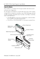
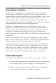
POINT I/O 24V dc Digital Diagnostics Input Module 7 Module Locking Mechanism Module Wiring Diagram DIN Rail Locking Screw (orange) Mechanical Keying (orange) Interlocking Side Pieces Slide-in Writable Label Insertable I/O Module Handle One-piece Terminal Base with Screw or Spring Clamp 44221 Publication 1734-IN029A-EN-E - January 2007
POINT I/O 24V dc Digital Diagnostics Input Module Before You Begin The module supports remove and insert under power, auto-address, and auto-baud in compliance with the POINTBus backplane. Each input is a sinking dc input with short-circuit and open-wire detection. The sensor source voltage is derived from the user auxiliary power and used as I/O power. Understand Short-circuit Detection The sensor source voltage (SSV) for each input is protected against short circuits.
POINT I/O 24V dc Digital Diagnostics Input Module 9 Understand Open-wire Detection Sensor source voltage (SSV) current for each input is monitored. Monitoring is accomplished in the SSV leg to accommodate the largest number of sensors possible. For currents below 0.5 mA, a fault signal is issued and the input's LED indicator blinks red. On a per-input basis, the circuit and produced data automatically reset upon removal of the open-wire condition.
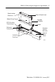
POINT I/O 24V dc Digital Diagnostics Input Module Slide the Mounting Base Until Side Pieces Engage Slide the mounting base until the interlocking side pieces engage the adjacent module or adapter. 31586 3. Press firmly to seat the mounting base on the DIN rail until the mounting base snaps into place.
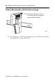
POINT I/O 24V dc Digital Diagnostics Input Module 11 Install the Module Install the module before or after base installation. Before installing the module into the mounting base be sure of this. • The mounting base is correctly keyed. • The mounting base locking screw is positioned horizontally referenced to the base. 1734-TB base is shown. Turn the keyswitch to align the number with the notch. Notch position 3 is shown. Be sure the DIN-rail locking screw is in the horizontal position.
POINT I/O 24V dc Digital Diagnostics Input Module Be sure the DIN-rail locking screw is in the horizontal position. 1734-TOP base is shown. Turn the keyswitch to align the number with the notch. Notch position 1 is shown.
POINT I/O 24V dc Digital Diagnostics Input Module 13 WARNING When you insert or remove the module while backplane power is on, an electrical arc can occur. This could cause an explosion in hazardous location installations. Be sure that power is removed or the area is nonhazardous before proceeding. Repeated electrical arcing causes excessive wear to contacts on both the module and its mating connector. Worn contacts may create electrical resistance that can affect module operation.
POINT I/O 24V dc Digital Diagnostics Input Module Insert the Module on the Base Insert the module straight down into the mounting base. Hook the RTB end into the mounting base end and rotate until it locks into place.
POINT I/O 24V dc Digital Diagnostics Input Module 15 Install the Removable Terminal Block When you connect or disconnect the removable terminal block (RTB) with field-side power applied, an electrical arc can occur. This could cause an explosion in hazardous location installations. WARNING Be sure that power is removed or the area is nonhazardous before proceeding.
POINT I/O 24V dc Digital Diagnostics Input Module Module Status Network Status Status - Input 0 Status - Input 1 Status - Input 2 Status - Input 3 Input 0 SSV 0 Input 1 SSV 1 Input 2 SSV 2 Input 3 SSV 3 41974 Note that voltage and current are daisychained from either the adapter, 1734-FPD module, or 1734-EP24DC module. Common connections for three-wire devices require an external wiring connection. A 1734-CTM module can provide the common connection.
POINT I/O 24V dc Digital Diagnostics Input Module 17 Wiring Sink Input Prox 0 1 In 0 V0 2 3 In 1 V1 In 2 V2 4 Prox Prox 5 6 7 In 3 Prox V3 V=10/28.8V dc If a common connection is required (three-wire devices), then a 1734-CTM common terminal module can be required. Channel 44226 Terminal Number Input Common Voltage 0 0 1 2 3 2 4 5 3 6 7 (1) External 1 Connect common on three-wire proximity switches. 10/28.8V dc is supplied through the internal power bus.
POINT I/O 24V dc Digital Diagnostics Input Module Configure the Module Read this section for information about how to communicate with your module. I/O messages are sent to (consumed) and received from (produced) the POINT I/O modules. These messages are mapped into the processor’s or scanner’s memory. This POINT I/O input module produces 1 or 2 bytes of input data based on which produced assembly is selected. The default setup is 2 bytes. It does not consume I/O data (scanner Tx).
POINT I/O 24V dc Digital Diagnostics Input Module 19 Default Data Map - Configuration Assembly Instance 103 Message Size: 18 Bytes 7 6 5 4 Consume 0 Input 0 Off to On Filter Byte 0 Consume 1 Input 0 Off to On Filter Byte 1 Consume 2 Input 0 On to Off Filter Byte 0 Consume 3 Input 0 On to Off Filter Byte 1 Consume 4 Input 1 Off to On Filter Byte 0 Consume 5 Input 1 Off to On Filter Byte 1 Consume 6 Input 1 On to Off Filter Byte 0 Consume 7 Input 1 On to Off Filter Byte 1 Consume 8 Input
POINT I/O 24V dc Digital Diagnostics Input Module Interpret the LED Indicators See the figure and table that show how to interpret LED indicators.
POINT I/O 24V dc Digital Diagnostics Input Module 21 Interpret LED Indicators Indication Probable Cause Recommended Action Off No power applied to device. Apply power to device. Green Device operating normally. None. Flashing Green Device needs commissioning due to configuration missing, incomplete or incorrect. Configure device properly. Flashing Red Recoverable fault. 1. Cycle power to device. 2. If condition persists, replace device.
POINT I/O 24V dc Digital Diagnostics Input Module Indication Probable Cause Recommended Action Off Device is not online. - Device has not completed dup_MAC_id test. - Device not powered - check module status indicator Apply power to device, wait for dup_MAC_id to complete, and correct, as needed. Flashing Green Device is on-line but has no connections in the established state. None - device is in Idle or Program mode. Green Device on-line and has connections in the established state. None.
POINT I/O 24V dc Digital Diagnostics Input Module 23 Indication Probable Cause Recommended Action Yellow Input is in the on state. None. Red Short circuit detected. Check I/O wiring or terminal base. Flashing Red Open wire detected. Check I/O wiring or terminal base. Remove a Mounting Base To remove a mounting base, you must first remove any installed module and the module installed in the base to the right. 1. For a module with a two-piece terminal base, use these steps; otherwise, use step 2.
POINT I/O 24V dc Digital Diagnostics Input Module Specifications POINT I/O 24V dc 4-channel Digital Diagnostics Input Module - 1734-IB4D Attribute Value Module Location 1734-TB, 1734-TBS, 1734-TOP, and 1734-TOPS bases POINTBus Current 50 mA max @ 5V dc Power Dissipation 0.6 W max @ 28.8V dc Thermal Dissipation 1.9 BTU/hr max @ 28.
POINT I/O 24V dc Digital Diagnostics Input Module 25 POINT I/O 24V dc 4-channel Digital Diagnostics Input Module - 1734-IB4D Attribute Value Off to On Filter, Max 65,535 us On to Off Filter, Min 0 us Off to On Filter, Max 65 535 us Environmental Specifications Attribute Value Temperature, operating IEC 60068-2-1 (Test Ad, Operating Cold), IEC 60068-2-2 (Test Bd, Operating Dry Heat), IEC 60068-2-14 (Test Nb, Operating Thermal Shock): -20…55 °C (-4…131 °F) Temperature, storage IEC 60068-2-1 (Test
POINT I/O 24V dc Digital Diagnostics Input Module Environmental Specifications Attribute Value Surge Transient Immunity IEC 61000-4-5: ±1 kV line-line (DM) and ±2 kV line-earth (CM) on signal ports Conducted RF Immunity IEC 61000-4-6: 10V rms with 1 kHz sine-wave 80%AM from 150 kHz…80 MHz Emissions CISPR 11: Group 1, Class A Enclosure Type Rating None (open-style) North American Temp Code T5 Wire Size 0.25... 2.5 mm2 (22...
POINT I/O 24V dc Digital Diagnostics Input Module 27 Certifications Attribute Value Certifications (when product is C-Tick Australian Radiocommunications Act, compliant with: AS/NZS CISPR 11; Industrial Emissions C-UL-us UL Listed Industrial Control Equipment, certified for US and Canada. See UL File E65584. UL Listed for Class I, Division 2 Group A,B,C,D Hazardous Locations, certified for U.S. and Canada. See UL File E194810.
Rockwell Automation Support Rockwell Automation provides technical information on the web to assist you in using its products. At http://support.rockwellautomation.com, you can find technical manuals, a knowledge base of FAQs, technical and application notes, sample code and links to software service packs, and a MySupport feature that you can customize to make the best use of these tools.