
Installation Instructions User guide

18 POINT I/O 24V dc Digital Diagnostics Input Module
Publication
1734-IN029A-EN-E - January 2007
Configure the Module
Read this section for information about how to communicate with
your module.
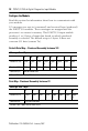
I/O messages are sent to (consumed) and received from (produced)
the POINT I/O modules. These messages are mapped into the
processor’s or scanner’s memory. This POINT I/O input module
produces 1 or 2 bytes of input data based on which produced
assembly is selected. The default setup is 2 bytes. It does not
consume I/O data (scanner Tx).
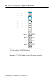
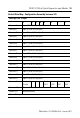
Default Data Map - Produced Assembly Instance 101
Message Size: 2 Bytes
76543210
Produce 0 (Rx) Fault
3
Fault
2
Fault
1
Fault
0
Input
3
Input
2
Input
1
Input
0
Produce 1 (Rx) SC 3 SC 2 SC 1 SC 0 OW 3 OW 2 OW 1 OW 0
Consume (Tx) No consumed data
Where: OW = open wire, SC = short circuit, fault = open wire or short circuit.
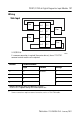
Data Map - Produced Assembly Instance 23
Message Size: 1 Byte
76543210
Produce 0 (Rx) Fault
3
Fault
2
Fault
1
Fault
0
Input
3
Input
2
Input
1
Input
0
Consume (Tx) No consumed data
Where: Fault = open wire or short circuit.