
Installation Instructions User Manual


POINT I/O 8 Channel High Density Current Input Modules 13
Publication
1734-IN033B-EN-P - November 2010
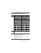
Default Data Map for the 1734-IE8C Analog Input Module
Message size: 24 Bytes
Byte 15 14 13 12 11 10 09 08 07 06 05 04 03 02 01 00
Produces
(scanner
Rx)
Input Channel 0 High Byte Input Channel 0 Low Byte
Input Channel 1 High Byte Input Channel 1 Low Byte
Input Channel 2 High Byte Input Channel 2 Low Byte
Input Channel 3 High Byte Input Channel 3 Low Byte
Input Channel 4 High Byte Input Channel 4 Low Byte
Input Channel 5 High Byte Input Channel 5 Low Byte
Input Channel 6 High Byte Input Channel 6 Low Byte
Input Channel 7 High Byte Input Channel 7 Low Byte
Status Byte for Channel 1 Status Byte for Channel 0
OR UR HHA LLA HA LA CM CF OR UR HHA LLA HA LA CM CF
Status Byte for Channel 3 Status Byte for Channel 2
OR UR HHA LLA HA LA CM CF OR UR HHA LLA HA LA CM CF
Status Byte for Channel 5 Status Byte for Channel 4
OR UR HHA LLA HA LA CM CF OR UR HHA LLA HA LA CM CF
Status Byte for Channel 7 Status Byte for Channel 6
OR UR HHA LLA HA LA CM CF OR UR HHA LLA HA LA CM CF
Consumes
(scanner
Tx)
No consumed data
Where: CF = Channel Fault status; 0 = no error, 1 = fault
CM = Calibration Mode; 0 = normal, 1 = calibration mode
LA = Low Alarm; 0 = no error, 1 = fault
HA = High Alarm; 0 = no error, 1 = fault
LLA = Low/Low Alarm: 0 = no error, 1 = fault
HHA = High/High Alarm; 0 = no error, 1 = fault
UR = Underrange; 0 = no error, 1 = fault
OR = Overrange; 0 = no error, 1 = fault