
Installation Instructions User Manual


18 POINT I/O 8 Channel High Density Current Input Modules
Publication
1734-IN033B-EN-P - November 2010
Input
impedance/resistance
conversion type
60 Ω
Sigma Delta
Common mode
rejection ratio
120 dB
Normal mode
rejection ratio
-60 dB
Notch Filter
15.7 Hz @ Notch = 60 Hz (default)
13.1 Hz @ Notch = 50 Hz
26.2 Hz @ Notch = 100 Hz
31.4 Hz @ Notch = 120 Hz
52.4 Hz @ Notch = 200 Hz
62.9 Hz @ Notch = 240 Hz
78.6 Hz @ Notch = 300 Hz
104.8 Hz @ Notch = 400 Hz
125.7 Hz @ Notch = 480 Hz
Data format Signed integer
Maximum overload Fault protected to 28.8V DC
Calibration Factory calibrated
Indicators 1 green/red network status indicator, logic side
1 green/red module status indicator, logic side
8 green/red input status indicators, logic side
(1)
Includes offset, gain, non-linearity and repeatability error terms
IMPORTANT
Refer to Publication 1734-SG001 for information on breaking the field power
distribution bus. Refer to sections “When to Use the Field Power
Distributor” and “When to Use the Expansion Power Unit”.
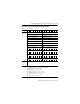
Input Specifications
Attribute Value