ArmorPoint I/O DeviceNet Adapters 1738-ADN12, 1738-ADN18, 1738-ADN18P, 1738-ADNX User Manual
Important User Information Solid state equipment has operational characteristics differing from those of electromechanical equipment. Safety Guidelines for the Application, Installation and Maintenance of Solid State Controls (Publication SGI-1.1 available from your local Rockwell Automation sales office or online at http://www.ab.com/manuals/gi) describes some important differences between solid state equipment and hard-wired electromechanical devices.
Preface Purpose of This Manual This manual describes how to install, configure, and operate your ArmorPoint I/O™ DeviceNet™ Adapters, catalog numbers 1738-ADN12, -ADN18, -ADN18P, and -ADNX.
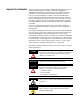
Preface 2 What the Manual Contains This manual contains the following sections: Chapter 1 - Install the ArmorPoint DeviceNet Adapters Chapter 2 - What Is the ArmorPoint DeviceNet Adapter? Description of how to install and wire the adapter Overview of the adapter’s features and functionality 1738-ADN12 DeviceNet Out DeviceNet In Adapter Status DeviceNet Status X10 PointBus Status X1 System Power R Adapter Power PWR Chapter 3 - Use Auto Start Mode Or Description of how to use the Auto Start
Preface Related Terms 3 This manual uses the following terms: Term: Definition: Adapter The adapter interfaces between DeviceNet devices and ArmorPoint I/O modules. ArmorPoint I/O DeviceNet adapters include the 1738-ADN12, -ADN18, -ADN18P, and -ADNX. Auto Catalog Replace The ArmorPoint I/O DeviceNet adapter supports the swapping of two identical modules connected to the adapter.
Preface 4 Publication 1738-UM001A-EN-P - February 2005 Term: Definition: Cyclic DeviceNet communications method in which the adapter sends data cyclically based on a configured time value. Data is independently received cyclically from the sender. Data in both directions can be acknowledged or unacknowledged depending on the run time configuration of the system. MACID Media Access Control Identifier (DeviceNet network address). Master A DeviceNet network device (e.g.
Preface Term: Definition: Subnet 1738-ADNX only. The Subnet DeviceNet network is defined as the DeviceNet link that provides the expansion of the PointBus to let the 1738-ADNX use its lower connector to add an additional 500 meters and up to 63 nodes. These nodes will be bridged through the 1738-ADNX up to the primary network. Note that backplane modules are also part of the Subnet.
Preface 6 If you need more information on these products, contact your local Rockwell Automation/Allen-Bradley distributor, integrator or sales office for assistance. For more information on the documentation, refer to the Allen-Bradley Publication Index, publication SD499. Guidelines for Using Your Adapter Remember the following operational guidelines when using your ArmorPoint DeviceNet adapter. • Do not leave spaces in the I/O. Instead, install all ArmorPoint I/O modules adjacent to each other.
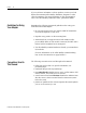
Table Of Contents Chapter 1 Install the ArmorPoint DeviceNet Adapters Mount the Adapter and I/O Base . . . . . . . . . . . . Set the Node Address . . . . . . . . . . . . . . . . . . . . Wire the DeviceNet Adapters. . . . . . . . . . . . . . . 1738-ADN12 and 1738-ADNX . . . . . . . . . . . . 1738-ADN18 and 1738-ADN18P . . . . . . . . . . 1738 ArmorPoint DeviceNet Auxiliary Power Chapter Summary and What’s Next . . . . . . . . . . . . . . . . . . . . . . . . . . . . . . . . . . . . . . . . . . . . . .
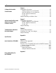
ii Chapter 4 Configure the DeviceNet Scanner Subnet Configuration Overview . . . . . . . . . . . . Add the Scanner To Your Network . . Add I/O Modules To Your Network . Set the Scanner’s Parameters. . . . . . . Go On Line . . . . . . . . . . . . . . . . . . . Chapter Summary and What’s Next . . . . . . . . . . . . . . . . . . . . . . . . . . . . . . . . . . . . . . . . . . . . . . . . . . . . . . . . . . . . . . . . . . . . . . . . . . . . . . . . . . . . . . . . 4-1 4-2 4-3 4-3 4-8 4-8 .
iii Appendix D Default Data Maps 1738-IA2 Input Module . . . . . . . . . . . . . . . . . . . . . 1738-IB2 Sink Input Module . . . . . . . . . . . . . . . . . . 1738-IB4 Sink Input Module . . . . . . . . . . . . . . . . . . 1738-IB8 Sink Input Module . . . . . . . . . . . . . . . . . . 1738-IV4 Source Input Module . . . . . . . . . . . . . . . . 1738-IV8 Source Input Module . . . . . . . . . . . . . . . . 1738-OA2 Output Module . . . . . . . . . . . . . . . . . . .
iv Publication 1738-UM001A-EN-P - February 2005
Chapter 1 Install the ArmorPoint DeviceNet Adapters This chapter describes how to install and wire your adapter. See the following sections: Mount the Adapter and I/O Base Page: Mount the Adapter and I/O Base 1-1 Set the Node Address 1-2 Wire the DeviceNet Adapters 1-3 Chapter Summary and What’s Next 1-4 To mount the ArmorPoint adapter on a wall or panel, use the screw holes provided in the adapter. A mounting illustration for the ArmorPoint adapter with I/O bases is shown below.
1-2 Install the ArmorPoint DeviceNet Adapters 5. Mount the terminating base that was shipped with the adapter as the last base in the backplane instead of the base that was shipped with the I/O module. Terminating base Mounting hole Ground connection Latching mechanism holes Set the Node Address 43787 Valid node addresses are 00 through 63. Set the node address using either the rotary switches, RSNetWorx for DeviceNet, DeviceNetManager, or another software configuration tool.
Install the ArmorPoint DeviceNet Adapters 1-3 The rotary switches are read periodically. If the switches have been changed since the last time they were read and they no longer match the on line address, a minor fault will occur, which is indicated by a flashing red Adapter Status LED. Settings of 64 through 99 cause the module to use the last valid node address stored internally. For example, the last setting internally was 40.
1-4 Install the ArmorPoint DeviceNet Adapters 1738 ArmorPoint DeviceNet Auxiliary Power 43587 ATTENTION Chapter Summary and What’s Next Publication 1738-UM001A-EN-P - February 2005 Male In Connector (view into connector) Pin 1 - User Power + Pin 2 - Adapter Power + Adapter/Subnet + (1738-ADNX only) Pin 3 - Adapter Power Adapter/Subnet - (1738-ADNX only) Pin 4 - User Power - Make sure all connectors and caps are securely tightened to properly seal the connections against leaks and maintain IP67 requi
Chapter 2 What Is the ArmorPoint DeviceNet Adapter? This chapter describes the ArmorPoint I/O DeviceNet adapter, including descriptions of the adapter’s features and functionality.
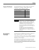
2-2 What Is the ArmorPoint DeviceNet Adapter? Use the Adapter The adapter resides on the primary DeviceNet network and the Subnet simultaneously. The PointBus maintains all DeviceNet network protocol but also offers configuration capabilities. IMPORTANT The adapter interfaces between DeviceNet devices and ArmorPoint I/O modules. The graphic below shows the adapter on the DeviceNet network and PointBus.
What Is the ArmorPoint DeviceNet Adapter? 2-3 1. Set Subnet/Backplane Baudrate The adapter and Subnet/Backplane modules must use the same baudrate to communicate with each other. Use one or both of the following to set a Subnet/Backplane baudrate. • Enable or disable the Backplane Autobaud feature for ArmorPoint I/O modules. ArmorPoint I/O modules have Autobaud enabled as the default- See page 2-12. • Set the adapter baudrate for the Subnet. The default for the 1738-ADN12, -ADN18, and -ADN18P is 1Mbaud.
2-4 What Is the ArmorPoint DeviceNet Adapter? 4. Configure the Primary DeviceNet Network Finally, you must configure the adapter for communication with a master (e.g., 1756-DNB). For more information on configuring the DeviceNet network, see Chapter 5, Add the ArmorPoint DeviceNet Adapter to the DeviceNet Scanner’s Scanlist. You must understand all of the adapter’s features to effectively use it in your ArmorPoint I/O system. Keep these four steps in mind as you read this manual: 1.
What Is the ArmorPoint DeviceNet Adapter? 2-5 Remove and Reinsert Modules on the Backplane Removal and Insertion Under Power (RIUP) is not recommended in a ArmorPoint System because of the following reasons. • Removing a module breaks the IP67 seal. • Removing a module breaks the backplane bus. Modules to the right of the removed module will be ‘lost’ to the adapter. Also, the terminating resistor will be removed, causing system uncertainty.
2-6 What Is the ArmorPoint DeviceNet Adapter? – If modules of the same type are removed and returned to the wrong locations, the adapter identifies the returned modules, updates their MACIDs, and continues operation. IMPORTANT The removal and return scenario exists whether the system is under power or not. If the system is under power, the scenario arises immediately. If the system is not under power, the scenario arises in the next power cycle.
What Is the ArmorPoint DeviceNet Adapter? 2-7 Backplane/Subnet Network On the Backplane/Subnet, your adapter acts as a scanner and is the master of the Subnet modules. The adapter performs the following functions: • Exchanges I/O data with devices on the Backplane/Subnet • Collects I/O data from the Backplane/Subnet and sends it to devices on the DeviceNet network (e.g.
2-8 What Is the ArmorPoint DeviceNet Adapter? Adapter Features Your adapter uses the following features on both the DeviceNet network and the PointBus: • • • • • Self-Test Field Upgradable Firmware Fully Configurable Software Connections Baudrates Self-Test When power is applied to the adapter, the adapter performs a self-test. The adapter tests various internal and programmatic memories and checks the status indicators (LEDs).
What Is the ArmorPoint DeviceNet Adapter? 2-9 You can use I/O mapping to determine the data contained in each connection. The adapter supports Master/Slave connection types on the DeviceNet network. On the Subnet, the adapter functions as a scanner device, exchanging data with I/O modules. Baudrates Choose baudrates for the adapter in the RSNetWorx for DeviceNet software.
2-10 What Is the ArmorPoint DeviceNet Adapter? Auto Catalog Replace Auto Catalog Replace corrects errors that might occur when backplane modules of the same type are removed and replaced in the wrong location. If modules of the same type are removed and returned to the wrong locations, the adapter identifies the returned modules, updates their MAC IDs, and continues operation.
What Is the ArmorPoint DeviceNet Adapter? 2-11 The baudrate may not take effect until power is recycled or the I/O modules are reset. IMPORTANT Changes to the Backplane/Subnet Baudrate parameter only take effect if they are downloaded on an individual basis. (For example, if you change the Backplane/Subnet Baudrate and download the changes with additional changes to other features, the Backplane/Subnet Baudrate remains at the previous setting.
2-12 What Is the ArmorPoint DeviceNet Adapter? Backplane Autobaud The adapter itself never autobauds on the Subnet. Backplane Autobaud automatically enables or disables Autobaud for all I/O modules currently attached to the backplane. The adapter does not set a specific rate though (as with Backplane Baudrate). If you enable Backplane Autobaud in the adapter or the EDS parameter access that you set from the primary DeviceNet, the adapter only enables the Autobaud in all backplane I/O modules.
What Is the ArmorPoint DeviceNet Adapter? 2-13 Auto Address The EDS parameter Auto Address is available from the primary DeviceNet and lets the user sequentially order the node addresses of backplane I/O modules. This parameter is not a mode but occurs on a single occurrence only. The node address selected is assigned to the module closest to the adapter. The next closest module is assigned the next numerically higher value. The numbering pattern continues for all connected backplane I/O modules.
2-14 What Is the ArmorPoint DeviceNet Adapter? Cycling Node Status Using the Cycling Node Status parameter, you can easily determine the status of any ArmorPoint I/O modules with which the adapter is experiencing problems. A corresponding text string appears, including the MAC ID, and a description of the status code reported in the Node Status Table. For more information on the Node Status Table, see page 2-24.
What Is the ArmorPoint DeviceNet Adapter? 2-15 Cycling I/O Mapping Cycling I/O Mapping is an EDS parameter accessible from the primary DeviceNet that shows you how data is mapped in the adapter’s scanlist. The data, as shown below, is listed in order of active modules in the scanlist.
2-16 What Is the ArmorPoint DeviceNet Adapter? The adapter is capable of holding approximately 64K of configuration data for ArmorPoint I/O modules connected to it. The adapter sends configuration data to an I/O module each time connections are created with that module (i.e., power cycle or module insertion to backplane). You can exchange an old module for a new one if the following conditions are met: • ADR is enabled in the adapter. • The new module matches the old one (i.e., electronic keying).
What Is the ArmorPoint DeviceNet Adapter? 2-17 Interscan Delay (ISD) Interscan Delay is the time delay between consecutive I/O scans of polled devices. The default setting is 10ms. The ISD=4ms for Auto Start Mode. You can change this parameter in the Module window of the scanner in the RSNetWorx for DeviceNet software. The scanner uses this period of time to perform non-time-critical communications on the DeviceNet network, such as communicating with RSNetWorx for DeviceNet software.
2-18 What Is the ArmorPoint DeviceNet Adapter? Transmit Retries Transmit Retries are the maximum number of times that the scanner will attempt to send an I/O message to a device before it times out and generates an error message. You set this parameter in the Module window (from the Advanced button) of the scanner in RSNetWorx for DeviceNet software.
What Is the ArmorPoint DeviceNet Adapter? 2-19 Overview of the Communication Process In a typical configuration, the adapter acts as an interface between a DeviceNet scanner (e.g., 1756-DNB) and ArmorPoint I/O modules. The following example graphic shows information transferred from a 1756-DNB to ArmorPoint I/O modules. IMPORTANT Although information is exchanged between the Logix5555 and 1756-DNB, this diagram (nor this chapter) is not designed to explain such an exchange.
2-20 What Is the ArmorPoint DeviceNet Adapter? The four data transfers are not necessarily sequential. Transfers 2 and 3 typically occur more frequently than transfers 1 and 4. Image Table Mapping Your adapter receives data from: • master devices (e.g., scanners) - output data is then passed to ArmorPoint I/O modules • input modules - input data is passed to the scanner The adapter must map the data it receives to its internal memory before passing it to the appropriate device.
What Is the ArmorPoint DeviceNet Adapter? 2-21 The following graphic shows how the adapter maps information.
2-22 What Is the ArmorPoint DeviceNet Adapter? See the I/O Status Word Bit Definitions table for definitions of the first 2 bytes of each I/O message produced by the adapter on DeviceNet. I/O Status Word Bit Definitions Bit 0 Operating Mode Operating Mode Description 0 = Run mode Run - The adapter maps output data to each module on PointBus.
What Is the ArmorPoint DeviceNet Adapter? Communicate With I/O Modules 2-23 The adapter module supports multiple communication choices. These choices all use the default I/O structure previously described. The adapter’s master (e.g., 1756-DNB) makes the actual communication choice. The choices are: • Polled – Adapter sends data in response to received data. • Strobe – Adapter sends data in response to the strobe command. The single bit allocated to the adapter in the strobe message is not used.
2-24 What Is the ArmorPoint DeviceNet Adapter? Use Diagnostic Tables The adapter maintains three diagnostic tables to manage the flow of data between a processor and a network’s devices. You can access the table over DeviceNet through the Scan Config Object (Class Code 0x90), Instance 1, via the following read-only attributes: • Faulted Node Table (Attribute 0xA) - In this 8-byte table, each bit represents a node on the backplane.
What Is the ArmorPoint DeviceNet Adapter? 2-25 Node Status Table Numeric Code Definitions Numeric Code: Text Message: Definition: Take this action: 77 Wrong Data Size Data size expected by the device does not match scan list entry. Reconfigure your module for correct transmit and receive data sizes. 78 No Such Device Slave device in scan list table does not exist. Add the device to the network, or delete scan list entry for that device.
2-26 What Is the ArmorPoint DeviceNet Adapter? A user program can monitor the Device Failure Bit in the I/O message(s) received from the adapter. When it has determined the bit set, you can read the Faulted Node Table and Node Status Table, using the Explicit Message Program Control Feature of the scanner device, to determine the module experiencing problems and the nature of those problems.
Chapter 3 Use Auto Start Mode This chapter describes how to use the Auto Start Mode with your ArmorPoint I/O DeviceNet adapters. See the following sections: Page: Why Use Auto Start Mode? 3-2 Install the I/O Module 3-4 Use RSNetWorx for DeviceNet 3-5 Begin Auto Start Mode 3-7 Use Custom Configuration 3-9 Chapter Summary and What’s Next 3-10 This chapter assumes you already have an ArmorPoint system mounted. There are five simple steps to the Auto Start Mode: 1. Install the I/O Module 2.
3-2 Use Auto Start Mode Why Use Auto Start Mode? Auto Start Mode offers you a quick and easy method of getting your ArmorPoint I/O system ‘up and running’. If your ArmorPoint I/O application can use default configuration, you should use Auto Start Mode to easily begin operations.
Use Auto Start Mode 3-3 How Is I/O Data Mapped Using Auto Start Mode? In Auto Start Mode, you can map I/O data in the adapter’s memory in one of the following ways: • • • • Byte Boundaries Word Boundaries Double Word Boundaries Fixed Boundaries Byte Boundaries Each node’s I/O data is mapped in the adapter’s memory at the next available byte. This option works best in applications that use Allen-Bradley PLCs and SLCs.
3-4 Use Auto Start Mode Requirement To Using Auto Start Mode Your ArmorPoint DeviceNet adapter must be free of I/O connections on DeviceNet when you use Auto Start Mode. If you attempt to use Auto Start Mode after another scanner device has established I/O connections with the adapter, your attempt to use Auto Start Mode will be rejected. When the adapter is configuring itself in Auto Start Mode, no other device can establish I/O connections to the adapter.
Use Auto Start Mode 3-5 Remove the Module From the Mounting Base To remove the module from the mounting base: 1. Put a flat blade screwdriver into the slot of the orange latching mechanism. 2. Push the screwdriver toward the I/O module to disengage the latch. The module will lift up off the base. 3. Pull the module off of the base. For more information on installing and wiring the multiple ArmorPoint I/O modules, see the installation instructions for each catalog number.
3-6 Use Auto Start Mode 3. Click OK to synchronize your offline and online configuration. The adapter appears on the screen. 4. Double click on the adapter icon. Double click on this icon. You can either: • Upload configuration from the device to update the software • Download configuration from the software to the device 5. Click Yes to upload configuration from the device.
Use Auto Start Mode Begin Auto Start Mode 3-7 After you upload the configuration from the device to the software, begin Auto Start Mode (ASM). 1. Double click on the adapter icon to open the adapter properties window. 2. Click on the Parameters tab. 3. Click on the right side of the Auto Start Mode line so that a menu appears. A. Click on the Parameters window. B. Use the Auto Start Mode pull-down menu to choose a mapping option. The options are described on page 3-3. 4.
3-8 Use Auto Start Mode • Check that MACIDs are set to proper values • Check scanlist – browse to Subnet and view scanlist, or look at mapping text – Make sure the scanlist was saved (if not, investigate why?) – If you are using the 1738-ADNX adapter, check the Max(imum) Backplane MACID parameter. It should equal the number of modules residing on the backplane.
Use Auto Start Mode 3-9 Use the following procedures to attempt to remedy a problem: • Verify that each non-backplane module’s address and baudrate have been set correctly. • Verify that each backplane module is configured to autobaud. The adapter’s EDS parameter Set Backplane Autobaud can be used to set each module’s autobaud parameter. It is necessary to cycle a module’s power before the autobaud parameter change takes effect.
3-10 Use Auto Start Mode Chapter Summary and What’s Next Publication 1738-UM001A-EN-P - February 2005 Auto Start Mode was discussed in this chapter. Move on to Chapter 4, Configure the DeviceNet Scanner Subnet or to Chapter 5, Add the ArmorPoint DeviceNet Adapter to the DeviceNet Scanner’s Scanlist.
Chapter 4 Configure the DeviceNet Scanner Subnet This chapter describes how to custom configure your scanner for use with ArmorPoint I/O modules. See the following sections: Page: Configuration Overview 4-1 Add the Scanner To Your Network 4-2 Add I/O Modules To Your Network 4-3 Set the Scanner’s Parameters 4-3 Go On Line 4-8 Chapter Summary and What’s Next 4-8 Your adapter works on two networks simultaneously and must be configured for each separately.
4-2 Configure the DeviceNet Scanner Subnet You must follow these steps during configuration: 1. Add the scanner to your network 2. Add I/O modules to your network 3. Set the scanner’s parameters 4. Go on line Add the Scanner To Your Network Follow these steps: 1. Start RSNetWorx for DeviceNet. 2. Add the scanner as shown below. 3 The scanner appears on the network. 1. Expand the list of communication adapters. 2. Select the 1738-ADN12 ArmorPoint Scanner.
Configure the DeviceNet Scanner Subnet 4-3 Add I/O Modules To Your Network After you add the scanner, you must add the modules connected to the scanner on the Subnet. In the offline mode, I/O modules must be added individually. Follow these steps: 1. Add modules as shown below. 1. Expand the Category to display the list of I/O modules. NOTE: Make sure you check under all the categories that I/O modules reside (i.e., General Purpose Discrete I/O, Rockwell Automation miscellaneous, and Specialty I/O).
4-4 Configure the DeviceNet Scanner Subnet General window Type the scanner’s name here. Type a description here (optional). The scanner’s address must = 0. This window also shows the scanner’s device identity. These fields are read-only. Click OK to accept the parameters. IMPORTANT: Configuration changes made in offline mode do not take effect until the scanner goes on line. For more information on how the scanner goes on line, see page 4-8.
Configure the DeviceNet Scanner Subnet 4-5 Module window Set the Interscan Delay here. Set the Foreground to Background Poll Ratio here. Click here to reset the Interscan Delay and Foreground to Background Poll Ratio back to the module default values. Click Advanced to change the advanced module settings, as shown in the following window. Advanced window accessed from Module window We recommend you DO NOT change module settings unless advised to do so by a Rockwell Automation support representative.
4-6 Configure the DeviceNet Scanner Subnet Input window Highlight a module and click Unmap to unmap it. Click Advanced to edit the advanced mapping parameters, as shown below. Click Options to edit the automap options, as shown below. Use this pull-down menu to choose a Memory type. Set the starting byte for I/O mapping. The memory type corresponds to an I/O connections on DeviceNet.
Configure the DeviceNet Scanner Subnet 4-7 Following are the remaining configuration windows. ADR window Use this screen to choose Automatic Device Replacement options. You must have loaded each device into RSNetWorx for DeviceNet before you can Load Device Config using this button. Summary window IMPORTANT: You cannot change any configuration parameters on this screen. It is for information purposes only.
4-8 Configure the DeviceNet Scanner Subnet Go On Line After you set configuration parameters, your scanner must go on line to accept the configuration changes. Follow these steps: 1. Use the Network pulldown to go on line. 1. Click on Network. 2. Click on Online. The software prompts you to save your configuration changes. Click Yes. 2. Choose your scanner’s network and apply the changes, as shown below. Select the DeviceNet network subnetwork.
Chapter 5 Add the ArmorPoint DeviceNet Adapter to the DeviceNet Scanner’s Scanlist This chapter describes how to custom configure your adapter for use with DeviceNet devices.
5-2 Add the ArmorPoint DeviceNet Adapter to the DeviceNet Scanner’s Scanlist You must follow these steps during configuration: 1. Add the adapter to your network 2. Set the adapter’s parameters 3. Add the DeviceNet adapter’s scanlist (see the Quick Start, Appendix B) 4. Go on line Add the Adapter to Your Network Follow these steps: 1. Start the RSNetWorx for DeviceNet software. 2. Add the adapter as shown below. 3 1. Expand the list of communication adapters. 2.
Add the ArmorPoint DeviceNet Adapter to the DeviceNet Scanner’s Scanlist 5-3 Set the Adapter’s Parameters After adding the adapter to the network, you must configure it for use with master DeviceNet devices. IMPORTANT This chapter shows configuration in the offline mode. Changes set in this mode do not take effect immediately.
5-4 Add the ArmorPoint DeviceNet Adapter to the DeviceNet Scanner’s Scanlist Device Bridging window Use Associate File to associate this configuration file with the configuration file that configures the same ArmorPoint DeviceNet scanner for communication with ArmorPoint I/O modules. Use Clear Association to remove previously established configuration file associations that no longer apply to your adapter.
Add the ArmorPoint DeviceNet Adapter to the DeviceNet Scanner’s Scanlist 5-5 The following screens show the remaining configuration windows. I/O Data window Connection sizes appear only when the Subnet network file has been associated in the Device Bridging window. These values correspond to the 4 parameters (Poll/COS Connection Consume Size, Poll Connection Produce Size, COS Connection Produce Size, Strobe Connection Produce Size) found in the device’s Parameters window.
5-6 Add the ArmorPoint DeviceNet Adapter to the DeviceNet Scanner’s Scanlist Go On Line Follow these steps for the adapter to go on line: 1. Use the Network pulldown. 1. Click on Network. 2. Click on Online. The software prompts you to save your configuration changes. Click Yes. 2. Choose your adapter’s network as shown below. Select the DeviceNet network. This selection accesses the PointBus to configure the adapter on the DeviceNet network. Click OK to apply the data to your adapter.
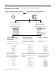
Chapter 6 Troubleshoot the ArmorPoint DeviceNet Adapter This chapter describes how to troubleshoot your adapter. See the following sections: Use the Status Indicators See page: Use the Status Indicators 6-1 Guidelines for Using Your Adapter 6-3 Chapter Summary 6-3 You can use the status indicators to troubleshoot your adapter. The following graphic shows the adapter’s status indicators.
6-2 Troubleshoot the ArmorPoint DeviceNet Adapter Indication Indication Probable Cause DeviceNet Status Off Device is not on line: - Device attempting to AutoBaud - Device has not completed dup_MAC_ID test - Device not powered - check module status indicator. Flashing Green Device is on line but has no connections in the established state. Green Device is on line and has connections in the established state. Flashing Red One or more I/O connection in timed-out state.
Troubleshoot the ArmorPoint DeviceNet Adapter Guidelines for Using Your Adapter 6-3 Remember the following operational guidelines when using your ArmorPoint DeviceNet adapter. • Do not leave spaces in the I/O. Instead, install all ArmorPoint I/O modules adjacent to each other. • Populate every position on the mounting base. • Do not add new I/O modules to the end of the ArmorPoint I/O system while the system is under power. • Use labels with the I/O modules.
6-4 Troubleshoot the ArmorPoint DeviceNet Adapter Notes: Publication 1738-UM001A-EN-P - February 2005
Appendix A Specifications Following are specifications for the 1738 ArmorPoint DeviceNet adapters. ArmorPoint DeviceNet Adapters - 1738-ADN12, -ADN18, -ADN18P, and -ADNX Expansion I/O Capacity • DeviceNet adapter backplane current output = 1.0 A maximum. See the following list for backplane current consumption for each ArmorPoint I/O catalog number and the current consumption for each of the ArmorPoint modules connected to the ArmorPoint DeviceNet adapter. Verify that it is below 1.0 A.
A-2 Specifications ArmorPoint DeviceNet Adapters - 1738-ADN12, -ADN18, -ADN18P, and -ADNX DeviceNet Power Specifications Power Supply Note: In order to comply with CE Low Voltage Directives (LVD), you must use either a NEC Class 2, a Safety Extra Low Voltage (SELV) or a Protected Extra Low Voltage (PELV) power supply to power this adapter. A SELV supply cannot exceed 30V rms, 42.4V peak or 60V dc under normal conditions and under single fault conditions.
Specifications A-3 ArmorPoint DeviceNet Adapters - 1738-ADN12, -ADN18, -ADN18P, and -ADNX General Specifications (continued) Relative Humidity IEC 60068-2-30 (Test Db, Un-packaged Non-operating Damp Heat): 5-95% non-condensing Shock IEC60068-2-27 (Test Ea, Unpackaged Shock): Operating 30 g Non-operating 50 g Vibration IEC60068-2-6 (Test Fc, Operating): 5 g @ 10-500 Hz ESD Immunity IEC 61000-4-2: 6 kV contact discharges 8 kV air discharges Radiated RF Immunity IEC 61000-4-3: 10V/m with 1 kHz sine-wave 80%A
A-4 Specifications Notes: Publication 1738-UM001A-EN-P - February 2005
Appendix B Quick Start For the 1738-ADNX What’s In This Appendix? In this Quick Start, you will learn how to use the 1738-ADNX with a ControlLogix system on DeviceNet. You will also use one of the 1738-ADNX’s features (Auto Start Mode) in an exercise to automatically configure devices on its Subnet.
B-2 Quick Start For the 1738-ADNX The new Subnet system attributes include: • Most field devices are more than 100 m from the ControlLogix Processor • Previously installed and documented at 500 Kbaud • 1738-ADNX with discrete inputs and outputs for several field devices • The ability to be replicated several times in the future without changing documentation. (i.e., devices will be replicated with same attributes, node addresses, etc.) The existing devices will be wired to ArmorPoint I/O.
Quick Start For the 1738-ADNX B-3 4. Click OK. Now that you have created a new DeviceNet project, go on line by clicking the Online icon on the toolbar. 5. A list of the available drivers in RSLinx appears. Drill down from Ethernet into your ControlLogix project through the backplane to your 1756-DNB in slot 3. Select channel A, as shown below. Your system may not be configured as illustrated.
B-4 Quick Start For the 1738-ADNX RSNetWorx will go on line. A screen similar to the one below will appear: Your system may not look like the above system. (You may have more nodes.) It is only important to verify that you have the 1756-DNB at node 0 and the 1738-ADNX at note 16. 8. After the browse is complete, from the RSNetWorx for DeviceNet main menu select File>Save As. 9. Type in MainNetworkADNX as the filename (use this exact name to avoid confusion later). 10. Click Save.
Quick Start For the 1738-ADNX B-5 c. Select the Scanlist tab and when prompted click Download. 12. When the download is complete, add the 1738-ADNX to the scanlist by selecting the 1738-ADNX (node 16) and clicking the single right arrow. A warning window opens that says that the 1738-ADNX does not contain any I/O data. At this point, RSNetWorx for DeviceNet does not know how many bytes of data are being inputted and outputted to the Subnet so it cannot fill in the values for you. 13.
B-6 Quick Start For the 1738-ADNX 15. Click Edit I/O Parameters. Click the 1738-ADNX in the Scanlist and then click Edit I/O Parameters to verify input and output bytes. 16. Verify that nothing is filled in for input and output sizes (both are zero). If you knew how much data was being produced and consumed on the Subnet, you could fill these fields in manually. Because it is easier to let RSNetWorx for DeviceNet fill in these values for us, click Cancel to close this window.
Quick Start For the 1738-ADNX B-7 17. Remove the 1738-ADNX from the scanlist for now by clicking the double arrows. Click the double left arrow to remove the 1738-ADNX from the Scanlist. Then verify that the Scanlist is empty. You will return here later after RSNetWorx for DeviceNet knows more about the devices on the Subnet. 18. Click OK. When prompted if you want to download changes to the device, click Yes.
B-8 Quick Start For the 1738-ADNX To properly terminate the 1738-ADNX when using a Subnet, refer to the illustration. 1738-ADNX With Subnet (1738-ADNX Subnet Drop Off Subnet Trunk) Main Trunk Terminator Resistor Terminator Resistor Drop Note that standard DeviceNet terminator resistors are shown in this illustration. Refer to the On-Machine Connectivity catalog, publication no. M115-CA001, Network Media section, for other DeviceNet connection options.
Quick Start For the 1738-ADNX B-9 21. Select the Parameters tab and choose Download. 22. Verify that your window looks similar to the following window. Review of the 1738-ADNX Rules and the MACID Parameter To understand some of the MACID parameters, you should review some of the rules for using the 1738-ADNX. • The 1738-ADNX always has address 0 on the Subnet. • All ArmorPoint I/O backplane module MACIDs must be numerically less than those of non-backplane Subnet modules.
B-10 Quick Start For the 1738-ADNX • The 1738-ADNX will automatically maintain the MACIDs of the backplane modules. • Note that the assignment of the MACIDs of the non-backplane subnet modules is manual and is not performed or retained by the 1738-ADNX. • The 1738-ADNX supports 125 kb, 250 kb, and 500 kb baudrates. For this example, you are going to set the Subnet to 125 kb. When using Auto Start Mode, the adapter: • • • • • • Sets all ArmorPoint I/O modules on the backplane to Autobaud.
Quick Start For the 1738-ADNX B-11 When Auto Start Mode is used, the adapter and connected I/O modules go through the following sequence of events: • Connections are established to I/O modules • The adapter makes Change of State (COS) connections if the I/O module supports COS, if not, the connection is Polled • Data is mapped to the connections The notes above explain parameter 1 – Max Backplane MACID. Next you will review parameter 6, Auto Start Mode and parameter 7, Fixed Map Size.
B-12 Quick Start For the 1738-ADNX Right now, the 1738-ADNX is not in another scanner’s scanlist so you can use the Auto Start Mode feature. By using Auto Start Mode, the 1738-ADNX will map all the devices on the Subnet and automatically adjust the value for the following parameters: • • • • • 1, Max Backplane MACID 9, Poll/COS Connection Consume Size 10, Poll Connection Produce Size 11, COS Connection Produce Size, and 12, Strobe Connection Produce Size. 2.
Quick Start For the 1738-ADNX B-13 Notice that parameters 9, 10, 11 and 12 are still at their default of 2 bytes. These values will be filled out for you when this action is complete. Download parameters to the device Monitor icon 4. Make sure All is selected and the Monitor value then click the icon to download parameters to the device (this triggers the Auto Start Mode). 5. Click the Monitor icon and notice: • Parameter 6 has gone back to Do Nothing.
B-14 Quick Start For the 1738-ADNX 6. Wait for parameter 8 to return to idle. Then click the Monitor icon to end monitoring. Notice the following: • Parameter 1 has been filled in for you. There are three ArmorPoint I/O modules in the backplane, causing the default to change from 31 to 3. • Parameter 3: Verify the Backplane Baudrate is 125 Kbaud. If it is not, you will need to find out why and make the necessary corrections. • Parameter 9, 10, 11, and 12 have been filled in for you.
Quick Start For the 1738-ADNX 8. From the RSNetWorx for DeviceNet main menu, select File>Save. IMPORTANT Browse the Subnet B-15 You must save your work before moving on. Look at the Subnet at this point to make things more clear. 1. From the RSNetWorx for DeviceNet main menu, select File>New and then select DeviceNet Configuration. 2. Click OK. Now that you have a new DeviceNet project created. 3. Click the Online icon. Last time you browsed to the 1756-DNB.
B-16 Quick Start For the 1738-ADNX 4. Drill down from Ethernet into your ControlLogix demo box through the backplane to your 1756-DNB in slot 3, channel A, 1738-ADNX and select DeviceNet Subnet as shown below: This time you will browse the Subnet Last time you browsed the main network 5. To go on line, click OK to accept the path configuration and then OK to the prompt. Wait for the browse to complete. 6. From the RSNetWorx for DeviceNet main menu, select File>Save As. 7.
Quick Start For the 1738-ADNX B-17 9. Verify your screen appears as shown below. The nodes can be in any order. Verify: • All four are there • They have the correct node numbers On the Subnet, the 1738-ADNX is a scanner and it is always at node 0. It is OK for some or all of the node numbers on the Subnet to be the same as devices on the primary network. Because they are two different networks, duplicate node errors will not occur.
B-18 Quick Start For the 1738-ADNX • Verify your scanlist matches that shown below. • Notice that all the ArmorPoint I/O modules have been added to the scanlist, as you probably expected. You are about to look at the input and output tabs. Based on your selections earlier, all the data should be mapped to word boundaries.
Quick Start For the 1738-ADNX B-19 Inputs and Outputs 1. Select the Input tab. A single word is 16 bits. Notice that the mapping is as expected. • The first two bytes (1 byte = 8 bits) are reserved as read only. • The first word is completely used, so the 1738-IB4M12 can map to the beginning of the next word (byte 2, bit 0). • There is a space between the 1738-IB4M12 and the 1738-OB4EM12 because the next word does not start until byte 4.
B-20 Quick Start For the 1738-ADNX Scroll down and notice that bytes 0 through 11 = 12 bytes total were enough for the input data. This matches what you observed earlier on the main network: Earlier view of the parameters. The primary network knew you were producing 12 bytes of data. • The data mapped in the 1738-ADNX will be exchanged with the 1756-DNB scanner. • There are three memory buffers that the 1738-ADNX uses for input data to the scanner on DeviceNet.
Quick Start For the 1738-ADNX B-21 2. Select the pulldown listbox next to the Memory label in the middle of the window to display the three memory buffer choices. 3. Select each of the choices and view the mapping. You will see that only the COS/cyclic buffer is being used (There are 2 bytes reserved for status in each buffer. These words are not for a specific module.) 4. Set the Memory selection back to COS/cyclic. Note that for the 1738-ADNX, each line in the mapping area represents a byte of data.
B-22 Quick Start For the 1738-ADNX You should still be looking at the subnet 1738-ADNX Input tab. Now select the Output tab and verify you have the following: • Notice that only the output module 1738-OB4EM12 appears. These two say read only, but since it is an output tab, a better description is reserved for future use. 5. Expand the plus next to node 2. • Several revisions ago (RSNetWorx for DeviceNet V3.21) the ability to view I/O details from the Input and Output windows was added into the software.
Quick Start For the 1738-ADNX B-23 6. Select Output Value #1 and notice the exact location of that bit is displayed. You can easily tell that Output Value #1 is in byte 2, bit 1 (see the highlighted portion of byte 2). This information will make it very easy to write your ladder logic later. You uploaded the scanlist and looked at the input and output data. Now you are about to save this information to your hard disk. 7. Click OK (not cancel) to close this window.
B-24 Quick Start For the 1738-ADNX 8. From the RSNetWorx for DeviceNet main menu, select File>Save. IMPORTANT You must save your work before moving on. Now all the information is saved in the file SubnetADNX.dnt. Navigate Between Networks A nice feature of RSNetWorx for DeviceNet is the easy way it lets you commission the Subnet. You can have two DeviceNet projects because there are actually two DeviceNet networks.
Quick Start For the 1738-ADNX B-25 2. Select the Device Bridging tab. The following window opens. This window lets you define a file that is associated with this one through the 1738-ADNX. Once you specify the associated file, you will be able to jump to that file through a menu selection from the 1738-ADNX. The file you need to associate in this case is the MainNetworkADNX.dnt project file you created earlier. 3. Click the Associate File button. 4.
B-26 Quick Start For the 1738-ADNX 7. From the RSNetWorx for DeviceNet main menu, select File>Save. Now you can observe how you would switch networks. Switch Between Networks 1. Move the cursor over the 1738-ADNX in the network browse window. 2. Press the right mouse button. 3. Click Associated Network from the menu. If prompted to save your changes, you must select Yes (you will probably not get this prompt if you saved earlier). To get back to the main network, associate the SubnetADNX.
Quick Start For the 1738-ADNX B-27 6. Click Associate File to associate the SubnetADNX.dnt file to the main network. 7. Press OK (not cancel) to save the association. Now that they are associated, you can easily jump between the main network and the Subnet and vice versa. Another advantage is that the main network has access to the information saved in Subnet.dnt. 8. Click the Online icon. 9. If prompted to save, click Yes. 10. At the prompt, click OK. 11.
B-28 Quick Start For the 1738-ADNX 13. Change the slot number to 3 (see illustration below) so it matches the 1756-DNBs location in the 1756-Rack. Then click the Scanlist tab. 2. Scanlist tab 1.
Quick Start For the 1738-ADNX B-29 14. Select the 1738-ADNX and then used the single right arrow key to add it to your scanlist. • Notice that you did not get the error message that you received earlier, when you were told that the 1738-ADNX ArmorPoint I/O DeviceNet Adapter does not contain any I/O data. • When you selected the Edit I/O Parameters button, you found that no values were filled in the Input and Output fields.
B-30 Quick Start For the 1738-ADNX Notice the fields have been filled in for you. The values match what was observed earlier. Values observed earlier. • The 1756-DNB scanner will be receiving 12 bytes of data that the 1738-ADNX produces. • The 1756-DNB scanner will be outputting 3 bytes of data that the 1738-ADNX consumes such as the 1738-OB4EM12 outputs.
Quick Start For the 1738-ADNX B-31 17. Click the Input tab and expand the plus sign next to the 1738-ADNX. Expand the plus sign If your mapping does not exactly match this screen, you may need to contact a Rockwell support engineer before moving on.
B-32 Quick Start For the 1738-ADNX Now select the Output tab and find the bit for Output Value #1 on the 1734-OB4EM12. It should be 3:O.Data[0].17 as shown below. (NOTE: Hold your cursor in the box above the highlighted area to cause the last number to display.) You are now ready to write your RSLogix5000 program. 18. Click Apply. 19. Click Yes when prompted to download these changes to the device. 20. Click OK to close the 1756-DNB Output window. 21. Exit RSNetWorx for DeviceNet.
Quick Start For the 1738-ADNX B-33 22. When prompted to save, Click Yes. You have completed the 1738-ADNX Quick Start.
B-34 Quick Start For the 1738-ADNX Notes: Publication 1738-UM001A-EN-P - February 2005
Appendix C Rules and Guidelines For the 1738-ADNX RULE 1: A DeviceNet Subnet may not bridge directly to another DeviceNet Subnet. A 1738-ADNX may not be used on the Subnet of another 1738-ADNX. NOTE: The 1738-ADNX will fault and report an error with any attempt to route message beyond the Subnet. It is not possible, therefore, to send explicit messages or browse through two 1738-ADNX adapters in series or through one 1738-ADNX and a network bridge device (or similar device) in series.
C-2 Rules and Guidelines For the 1738-ADNX RULE 9: Subnet modules not on the backplane must always have or be assigned MACID’s higher than those of the backplane modules. RULE 10: Power must be supplied for non-backplane Subnet modules. The 1738-ADNX supplies only 5V dc power to the backplane ArmorPoint I/O modules, and 24V dc power to the non-backplane modules via the auxiliary power connector, pins 2 and 3.
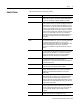
Appendix D Default Data Maps I/O messages are sent to (consumed) and received from (produced) the ArmorPoint I/O modules. These messages are mapped into the processor’s memory. This appendix lists the default data maps for 1738 ArmorPoint I/O modules.
D-2 Default Data Maps 1738-IA2 Input Module Message size: 1 Byte 7 6 5 4 3 2 Produces (scanner Rx) Consumes (scanner Tx) 1 0 Ch1 Ch0 1 0 Ch1 Ch0 No consumed data Where: Ch0 = channel 0, Ch1 = channel 1; 0 = OFF, 1 = ON 1738-IB2 Sink Input Module Message size: 1 Byte 7 6 5 4 3 2 Produces (scanner Rx) Consumes (scanner Tx) No consumed data Where: Ch0 = channel 0, Ch1 = channel 1; 0 = OFF 1 = ON 1738-IB4 Sink Input Module Message size: 1 Byte 7 Produces (scanner Rx) Consumes (scanne
Default Data Maps D-3 1738-IB8 Sink Input Module Message size: 1 Byte Produces (scanner Rx) 7 6 5 4 3 2 1 0 Ch7 Ch6 Ch5 Ch4 Ch3 Ch2 Ch1 Ch0 Consumes (scanner Tx) No consumed data Where: Ch0 = input channel 0, Ch1 = input channel 1, Ch2 = input channel 2 Ch3 = channel 3, Ch4 = input channel 4, Ch5 = input channel 5, Ch6 = input channel 6 Ch7 = channel 7; 0 = OFF, 1 = ON 1738-IV4 Source Input Module Message size: 1 Byte 7 6 5 4 Produces (scanner Rx) Consumes (scanner Tx) 3 2 1 0
D-4 Default Data Maps 1738-OA2 Output Module Message size: 1 Byte 7 6 5 4 Produces (scanner Rx) 3 2 1 0 Ch1 Ch0 No produced data Consumes (scanner Tx) Not used Channel state Where: Ch0 = output channel 0, Ch1 = output channel 1; 0 = OFF, 1 = ON 1738-OB2E Electronically Protected Output Module Message size: 1 Byte 7 6 5 Produces (scanner Rx) 4 3 2 Not used 1 0 Ch1 Ch0 1 0 Ch1 Ch0 Channel status Where: Ch0 = output channel 0, Ch1 = output channel 1; 0 = no error 1 = error M
Default Data Maps D-5 1738-OB4E Electronically Protected Output Module Message size: 1 Byte 7 6 Produces (scanner Rx) 5 4 Not used 3 2 1 0 Ch3 Ch2 Ch1 Ch0 Channel status Where: Ch0 = output channel 0, Ch1 = output channel 1, Ch2 = output channel 2, Ch3 = output channel 3; 0 = no error 1 = error Message size: 1 Byte 7 6 Consumes (scanner Tx) 5 4 Not used 3 2 1 0 Ch3 Ch2 Ch1 Ch0 Channel state Where: Ch0 = output channel 0, Ch1 = output channel 1, Ch2 = output channel 2, Ch3 =
D-6 Default Data Maps 1738-OV4E Protected Sink Output Module Message size: 1 Byte 7 6 Produces (scanner Rx) 5 4 Not used 3 2 1 0 Ch3 Ch2 Ch1 Ch0 Channel status Where: Ch0 = output channel 0, Ch1 = output channel 1, Ch2 = output channel 2, Ch3 = output channel 3; 0 = no error 1 = error Message size: 1 Byte 7 6 Consumes (scanner Tx) 5 4 Not used 3 2 1 0 Ch3 Ch2 Ch1 Ch0 Channel state Where: Ch0 = output channel 0, Ch1 = output channel 1, Ch2 = output channel 2, Ch3 = output cha
Default Data Maps D-7 1738-IE2C Analog Current Input Module Message size: 6 Bytes 15 14 Produces (scanner Rx) OR UR 13 12 11 10 09 08 07 06 05 04 03 02 Input Channel 0 High Byte Input Channel 0 Low Byte Input Channel 1 High Byte Input Channel 1 Low Byte Status Byte for Channel 1 Status Byte for Channel 0 HHA LLA Consumes (scanner Tx) HA LA CM CF OR UR HHA LLA HA LA 01 00 CM CF No consumed data Where: CF = Channel Fault status; 0 = no error, 1 = fault CM = Calibration
D-8 Default Data Maps 1738-IE2V Analog Input Module Message size: 6 Bytes 15 14 Produces (scanner Rx) OR UR 13 12 11 10 09 08 07 06 05 04 03 02 Input Channel 0 - High Byte Input Channel 0 - Low Byte Input Channel 1 - High Byte Input Channel 1 - Low Byte Status Byte for Channel 1 Status Byte for Channel 0 HHA LLA Consumes (scanner Tx) Where: CF = Channel Fault status; 0 = no error, 1 = fault CM = Calibration Mode; 0 = normal, 1 = calibration mode LA = Low Alarm; 0 = no error, 1 = fa
Default Data Maps D-9 1738-OE2C Analog Current Output Module Message size: 4 bytes 15 14 13 Consumes (Tx) 12 11 10 09 08 07 06 05 04 03 02 Output Channel 0 High Byte Output Channel 0 Low Byte Output Channel 1 High Byte Output Channel 1 Low Byte 01 00 01 00 Message size: 2 Bytes 15 14 13 Produces (Rx) 12 11 10 09 08 07 06 High Byte - Channel 1 Status Not used HCA LCA 05 04 03 02 Low Byte - Channel 0 Status CM CF Not used HCA LCA CM CF 03 02 01 00 CM ST
D-10 Default Data Maps 1738-IJ Encoder/Counter Module Message size: 6 Bytes 15 14 13 12 11 10 Produces (scanner Rx) 09 08 07 06 05 04 03 02 01 00 Channel 0 value of present counter state (LSW) Channel 0 value of present counter state (MSW) PE EF NR 0 0 0 0 0 0 ZS BS AS C1 C0 ZD 0 06 05 04 03 02 01 00 CM CF Where: PE = Programming error EF = EEPROM fault status NR = Not ready status bit ZS = Z input status BS = B input status AS = A input status C = Stored data cou
Default Data Maps D-11 1738-IT2I Isolated Thermocouple Input Module Message size: 8 Bytes 15 14 Produces (scanner Rx) OR UR OR UR 13 12 11 10 09 08 07 06 05 04 03 02 Input Channel 0 - High Byte Input Channel 0 - Low Byte Input Channel 1 - High Byte Input Channel 1 - Low Byte Status Byte for Channel 1 Status Byte for Channel 0 HHA LLA Consumes (scanner Tx) HA LA CM CF OR UR HHA LLA HA LA 01 00 CM CF Cold Junction Temperature (Selectable: Channel 0, Channel 1, or Aver
D-12 Default Data Maps 1738-VHSC 24V dc High Speed Counter Module Message size: 6 Bytes 15 14 13 12 11 Produces (scanner Rx) 10 09 08 07 06 05 04 03 02 01 00 C1 C0 ZD 0 Channel 0 value of present counter state (LSW) Channel 0 value of present counter state (MSW) PE EF NR 0 FS FS OS OS 0 ZS BS AS Where: PE = Programming error EF = EEPROM fault status NR = Not ready status bit FS = Output fault status bit - bit 10 for output 0, bit 11 for output 1 OS = Output on/off status b
Default Data Maps D-13 1738-232ASC ASCII Module Default Receive Data Assembly Format (Default Mode) Byte 1 Byte 2 Rx Transaction ID Byte Status Byte Byte 3 Reserved Byte 4 Length Byte 5-23 ASCII Data Byte 24 (Terminator) Default Transmit Data Assembly Format (Default Mode) Byte 1 Byte 2 Reserved Byte 3 TX Transaction ID Byte Reserved Byte 4 Length Byte 5-23 ASCII Data Byte 24 (Terminator) 1738-485ASC ASCII Module Default Receive Data Assembly Format (Default Mode) Byte 1 Byte 2
D-14 Default Data Maps Notes: Publication 1738-UM001A-EN-P - February 2005
Index Numbers 1734-IV8 data map D-3 1738-232ASC data map D-13 1738-485ASC data map D-13 1738-ADNX MACID parameter B-9 rules on how to use C-1 1738-ADNX quick start B-1 assumptions B-1 browse the subnet B-15 inputs and outputs B-19 navigate between networks B-24 review 1738-ADNX rules B-9 review auto start mode B-11 switch between networks B-26 1738-IA2 data map D-2 1738-IB2 data map D-2 1738-IB4 data map D-2, D-3 1738-IE2V data map D-8 1738-IEC2 data map D-7 1738-IJ data map D-10 1738-IR2 data map D-10 1738
2 auto start mode review 1738-ADNX B-11 autoaddress 2-13 adapter 5-4 enabling in RSNetWorx for DeviceNet 5-4 autoaddress backplane modules adapter 5-4 autobaud P-3, 2-9 automatic device replacement 2-15 automatic device replacement via PointBus 2-18 B backplane set I/O module address 2-3 backplane autobaud 2-12 adapter 5-4 enabling in RSNetWorx for DeviceNet 5-4 backplane baudrate 2-10 adapter 5-4 setting 2-3 setting in RSNetWorx for DeviceNet 5-4 backplane network 2-7 baudrate P-3, 2-9 browse the netwo
3 default data maps D-1 device bridging 5-4 DeviceNet communications backplane autobaud 2-12 backplane baudrate 2-10 change of state P-3, 2-6, 2-23 cyclic P-4, 2-6, 2-23 polled P-4, 2-6, 2-23 strobe P-4, 2-6, 2-23 DeviceNet network 2-6 remove and reinsert modules 2-5 RSNetwork for DeviceNet 2-2 understanding 2-6 DeviceNet network, primary configure 2-4 diagnositc tables 2-24 documentation other ArmorPoint I/O products 2-7, P-5 double word boundaries 3-3 I I/O data parameter adapter 5-5 I/O modules install
4 P parameters 1738-ADNX MACID B-9 adapter 5-4 foreground to background poll ratio 4-5 I/O data, adapter 5-5 map from scanner 4-6 scanner 4-3 scanner data alignment 4-6 scanner expected packet rate setting 4-5 scanner interscan delay 4-5 scanner transmit retries 4-5 setting adapter 5-3 physical list acquire status 2-13 physical ordering 2-16 PointBus 2-2 data collection 2-7 poll/COS connection consume size 2-14 polled P-4, 2-6, 2-23 power expansion power unit 2-7 supplying power to ArmorPoint I/O modules
5 scanner setting in RSNetWorx for DeviceNet 4-5 troubleshooting using status indicators 6-1 U updating adapter firmware using the ControlFlash utility P-3 using diagnostic tables 2-24 using the adatpers guidelines P-6 W wire the adapters 1-3 word boundaries 3-3 Publication 1738-UM001A-EN-P - February 2005
6 Publication 1738-UM001A-EN-P - February 2005
How Are We Doing? Your comments on our technical publications will help us serve you better in the future. Thank you for taking the time to provide us feedback. You can complete this form and mail it back to us, visit us online at www.ab.com/manuals, or email us at RADocumentComments@ra.rockwell.com Pub. Title/Type ArmorPoint I/O DeviceNet Adapters Cat. No. 1738-ADN12, -ADN18, Pub. No. -ADN18P, -ADNX 1738-UM001A-EN-P Pub. Date February 2005 Part No. 957899-58 Please complete the sections below.
PLEASE FASTEN HERE (DO NOT STAPLE) PLEASE FOLD HERE NO POSTAGE NECESSARY IF MAILED IN THE UNITED STATES BUSINESS REPLY MAIL FIRST-CLASS MAIL PERMIT NO.
Rockwell Automation Support Rockwell Automation provides technical information on the web to assist you in using our products. At http://support.rockwellautomation.com, you can find technical manuals, a knowledge base of FAQs, technical and application notes, sample code and links to software service packs, and a MySupport feature that you can customize to make the best use of these tools.