
User Manual Manual


Rockwell Automation Publication 1734-UM014B-EN-P - June 2013 11
Install Your Adapter Chapter 2
Mount the I/O Adapter
Use the following procedures to mount the I/O adapters on a new system before
you install any I/O modules.
Mount a 1734-FPD module in the slot next to the I/O adapter when applying
field power. You can also use the 24V DC to power the adapter to supply field
power, where no FPD is necessary. Refer to Point I/O Field Potential
Distribution Module Installation Instructions, publication 1734-IN059
for more
information.
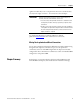
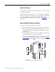
Mount the POINT I/O Adapter on a DIN Rail
Position the I/O adapters vertically above the DIN rail.
1. Make sure the DIN rail locking screw (orange) is in horizontal position.
2. Position the adapter vertically above an IEC standard (35 x 7.5 x 1 mm)
top-hat DIN rail at a slight angle (DIN rail: Allen-Bradley part number
199-DR1; 46277-3).
3. Press down firmly to install the adapter on the DIN rail, noting that the
locking mechanism locks the adapter to the DIN rail.
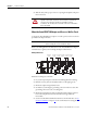
4. Set the network address thumbwheel switches to the desired value.Set the
network address thumbwheel switches to the desired value. See Set the
Network Address in chapter 3 for more details on setting the IP address.
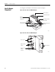
1734-AENTR
Module
Status
Network
Activity
Network
Status
Point Bus
Status
System
Powe
r
Field
Powe
r
POINT I O
75.30
(2.96)
74.00
(2.91)
132.72
(5.23)
52.23
(2.06)
35.55
(1.40)
A
B
45174
A = DIN rail
B = Secure DIN rail approximately every 200 mm (7.8 in.)