
User guide


Publication 1746-UM002B-EN-P - August 2004
Application Examples 6-9
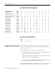
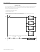
Ladder File 9 - HSCE2 Initialization Routine
Programming ladder file 9 shows the indirect addressing required to
set up the programming blocks in this example.
0000
LES
Less Than (A<B)
Source A N11:0
170<
Source B N11:1
170<
LES O:1
15
I:1
15
COP
Copy File
Source #N10:[N11:0]
Dest #O:1.0
Length 8
COP
L
O:1
15
0001
O:1
15
I:1
15
U
O:1
15
MEQ
Masked Equal
Source I:1.0
265<
Mask 6000h
24576<
Compare 0
0<
MEQ ADD
Add
Source A N11:0
170<
Source B 10
10<
Dest N11:0
170<
ADD
0002
EQU
Equal
Source A N11:0
170<
Source B N11:1
170<
EQU O:1
15
I:1
15
COP
Copy File
Source #N10:[N11:0]
Dest #O:1.0
Length 8
COP
L
B3:0
0
0003
0004
END
DATA_BLOCK_PTR
DATA_BLOCK_PTR
DATA_BLOCK_PTR
#HSCE2_CFG_BLK
#HSCE2_CFG_BLK
HSCE2_INIT_DONE
HSCE2_XMIT
1746-HSCE2
HSCE2_XMIT
1746-HSCE2
HSCE2_XMIT
1746-HSCE2
1746-HSCE2
HSCE2_ACK
HSCE2_XMIT
1746-HSCE2 1746-HSCE2
HSCE2_ACK
HSCE2_XMIT
1746-HSCE2 1746-HSCE2
HSCE2_ACK
L
B3:0
1
I:1
15
I:1
14
I:1
13
HSCE2_ACK
HSCE2_FAULT
1746-HSCE2
1746-HSCE2
1746-HSCE2
HSCE2_PERR
HSCE2_ERROR
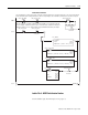
If the blocks have not all been transmitted (block data offset < max block offset), copy block to the HSCE2 and set transmit bit (O:e.0/15).
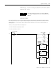
When HSCE2 sets its acknowledge bit (I:e.0/15), reset the module transmit bit (O:e.0/15) and check HSCE2
error bits (I:n.1). If no error bits are ON, increment the block counter to permit the next move to start.
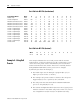
When the last block is completed (block data offset = max block offset), copy the Counter Control Block to the HSCE2.
Note: The Counter Control Block does not require a 0-1 positive transition of the transmit bit to operate.
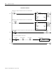
If the programming error bit or the module fault bit is set, set the HSCE2 error bit.