
User guide


1 Publication 1746-UM002B-EN-P - August 2004
Appendix
C
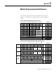
Module Programming Quick Reference
The module programming blocks are duplicated below for your
reference. A column has been added to show corresponding hex
values.
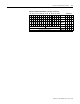
Figure C.1 Module Setup Block (see pages 4-6 to 4-10)
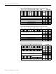
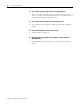
Figure C.2 Counter Configuration Block (see pages 4-10 to 4-13)
15 14 13 12 11 10 09 08 07 06 05 04 03 02 01 00 Hex Format
TRMT
0 0
DEBUG
0 0 0 0 0 0 0 0 0 0 01
Word 0
(1)
(1) 0 for normal operation. 1 for debug mode.
0 0 1
0 0 0 0 0
INT
RVF
PRA
0 0 0 0 0 0
Op Mode
Word 1
0 0
0 0 0 0 0 0 0 0 0 0 0
Counter 1
Range Allocation
Word 2
0 0
0 0 0 0 0 0 0 0 0 0 0
Counter 2
Range Allocation
Word 3
0 0
0 0 0 0 0 0 0 0 0 0 0
Counter 3
Range Allocation
Word 4
0 0
RESERVED: Must equal 0
Word 5
0 0 0 0
RESERVED: Must equal 0
Word 6
0 0 0 0
RESERVED: Must equal 0
Word 7
0 0 0 0
15 14 13 12 11 10 09 08 07 06 05 04 03 02 01 00 Hex Format
All
Counters
TRMT
0 0
DEBUG
PGM4
PGM3
PGM2
PGM1
0 0 0 0 0 010
Word 0
(1)
0 2
Counter 1
0 0 0 0 0 0 0 0 0 G/P Mode
Input
Config
CType
Word 1
0 0
0
Word 2
Counter 2
0 0 0 0 0 0 0 0 0 G/P Mode
Input
Config
CType
Word 3
0 0
0
Word 4
Counter 3
or 4 as
indicated
0 0 0 0 0 0
G/Pmode
CType
0 0 0 0 0 0
G/Pmode
CType
Word 5
0 0
Counter 4 Counter 3
0
Word 6
0
Word 7
(1) 0 for normal operation. 1 for debug mode.