
User guide


Publication 1746-UM002B-EN-P - August 2004
Configuration and Programming 4-9
Range Allocation Examples
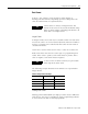
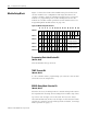
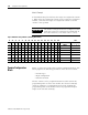
Mode 1 Example
In the Module Setup block below, 4 ranges are assigned to Counter 1.
The remaining 12 are assigned to Counter 2. The last counter is not
specified.
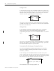
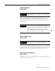
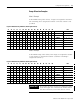
Mode 2 Example
In the Module Setup block below, four ranges are assigned to Counter
1. Four ranges are assigned to Counter 2, with the remaining 8
assigned to Counter 3.
Figure 4.2 Module Setup in Mode 1 (Showing Hex Format)
15 14 13 12 11 10 09 08 07 06 05 04 03 02 01 00 Hex
0000000000000001 Word 0 0001
0000000100000001 Word 1 0101
0000000000000100 Word 2 0004
0000000000000000 Word 3 0000
0000000000000000 Word 4 0000
0000000000000000 Word 5 0000
0000000000000000 Word 6 0000
0000000000000000 Word 7 0000
Figure 4.3 Module Setup in Mode 2 (Showing Hex Format)
15 14 13 12 11 10 09 08 07 06 05 04 03 02 01 00 Hex
0000000000000001 Word 0 0001
0000000100000010 Word 1 0101
0000000000000100 Word 2 0004
0000000000000100 Word 3 0004
0000000000000000 Word 4 0000
0000000000000000 Word 5 0000
0000000000000000 Word 6 0000
0000000000000000 Word 7 0000
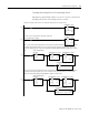
IMPORTANT
The number of ranges for the last configured counter
used must equal zero, otherwise the module fills in
the value and errors, even if the value is correct.