
User guide


Publication 1746-UM002B-EN-P - August 2004
Application Examples 6-7
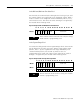
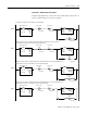
Data Table for N10 File (hexidecimal)
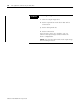
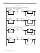
Data Table for N11 File (decimal)
Example 2 - Indirect
Addressing
In this example, the module is set up in Class 4, mode 1 using only
two counters. This example uses indirect addressing, which is
compatible only with SLC 5/03 or higher processors.
Programming Blocks Offset 0123456789
Module Setup N10:0 1 103 8 0 000000
Counter Configuration N10:10 F02 6 0 6 000000
Min/Max Count Value Counter 1 N10:20 400019000000
Min/Max Count Value Counter 2 N10:30 104 0 0 0 1F4 00000
Min/Max Count Value Counter 3 N10:40 204 0 0 0 258 00000
Min/Max Count Value Counter 4 N10:50 304 0 0 0 2BC 00000
Program Ranges N10:60 10 1 0 0 0 31 1 0 0 0
Program Ranges N10:70 10 2 0 32 0 63 2 0 0 0
Program Ranges N10:80 10 4 0 64 0 95 4 0 0 0
Program Ranges N10:90 10 8 0 96 0 C7 8 0 0 0
Program Ranges N10:100 10 10 0 C8 0 F9 1 0 0 0
Program Ranges N10:110 10 20 0 FA 0 12B 2 0 0 0
Program Ranges N10:120 10 40 0 12C 0 15D 4 0 0 0
Program Ranges N10:130 10 80 0 15E 0 190 8 0 0 0
Counter Control N10:140 80 8001 8001 8001 8001 FF00 FF 0 0 0
N10:15000000000
Offset 0123456789
N11:0 140 140 14
TIP
This example may be used with any mode (1, 2, or
3) and with any SLC 5/03 or higher processor, as
long as the module is in a local chassis. However,
the N10 and N11 data files would need to be
modified for a different configuration.