
INSTALL INSTRUC MOLD PRESSURE Manual
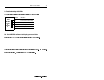

Mold Pressure Module 11
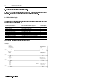
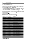
6. Set sensor inputs to zero
7. Check channel operation
For this type of sensor: Zero it: with: With this method:
hydraulic pressure (lo-level),
or injection pressure (hi-level)
a jumper, manually momentarily short “zero” terminal (4) to
“shield” terminal (5 or 6) after wiring,
once at setup.
mold pressure (lo-level) ladder logic
(channel selectable)
each machine cycle, toggle bit 04 (chnl 1)
or bit 05 (chnl 2) in output image word 0
(Rising-edge enabled, may remain ON for
the cycle, typically triggered on the mold-
closed bit (trigger 4).)
autozero feature of
DARTWin software
(channel selectable)
enabled on DARTWin’s Mold Setup screen
Software stores first value and subtracts it
from subsequent values any machine cycle.
both types (channels 1, 2) Each method works independently. While “zero” is ON, module
returns status bit 09 (chnl 1) or 10 (chnl 2) in input image word 0.
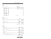
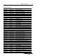
If
configured:
with
resistor
connect to module terminal block:
for internal
cal resistor
in module
(200K)
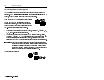
a) short “Cal” (terminal 3) to “Shld”
(terminal 5 for channel 1 or 6 for channel 2)
for external
cal resistor
in sensor b) cal resistor between “Cal R” and “Cal”
(between terminals 7 & 9 for channel 1,
or terminals 8 & 10 for channel 2)
separate
from
sensor
c) make two connections:
• resistor between “Cal R” and “+Sgnl”
(between terminals 7 & 13 for channel 1,
or terminals 8 & 14 for channel 2)
• jumper wire between “Cal” and “+Exc”
(between terminals 9 & 11 for channel 1,
or terminals 10 & 12 for channel 2)