
Installation Instructions Manual

Publication 1746-IN025A-EN-P - June 2002 PN 40071-147-01(1)
Supersedes Publication 40063-139-01(A) - August 1992 © 2002 Rockwell International Corporation. Printed in the U.S.A.
Assembly Procedure for Crimp Contacts
The following details the assembly procedure for the crimp type contacts.
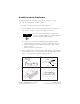
1. Strip the wire insulation as shown in Figure 1.
2. Insert the wire up to the wire stop as shown in Figure 2.
3. Crimp with DDK crimp tool 357J-5538. Equivalent Amp part numbers are:
pin - 87666-2, connector - 102387-9, and crimp tool - 90418-1.
If a crimp tool is not available, used the following crimping procedure:
a. Crimp the wire barrel around the wire using a small needle nose pliers.
b. Crimp the insulation barrel around the wire insulation using a small
needle nose pliers.
c. Solder wire and wire barrel together.
4. After completing above assembly, insert the cable into the socket housing as
shown in Figures 3 and 4. Check to make sure that the tang, shown as “A” in
Figure 4, is properly latched by gently pulling on the wire.
TIP
Pins and connectors from different manufacturers
cannot be assembled together. For example, Amp pins
cannot be used with a DDK connector.
4 mm
(5/32 in)
4 mm
(5/32 in)
A
4 mm
(5/32 in)
4 mm
(5/32 in)
A
Figure 1
Figure 2
Figure 3
Figure 4
Tang
Wire Stop