Installation Instructions SLC 500 8-Point Analog Output Module (Catalog Numbers 1746-NO8I and 1746-NO8V) Inside…............................................................................................page Important User Information .................................................................... 2 For More Information.............................................................................. 3 Hazardous Location Considerations .......................................................
SLC 500 8-Point Analog Output Module Important User Information Because of the variety of uses for the products described in this publication, those responsible for the application and use of these products must satisfy themselves that all necessary steps have been taken to assure that each application and use meets all performance and safety requirements, including any applicable laws, regulations, codes and standards.
SLC 500 8-Point Analog Output Module 3 For More Information Related Publications Table 1 List of Related Publications for 1746-NO8I and 1746-NO8V Modules For Refer to this Document Pub. No. A more detailed description on how to install and use your 1746-NO8 module. SLC 500 8-Point Analog Output Module User Manual 1746-UM026 A more detailed description on how to install and use your modular SLC 500 system.
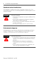
SLC 500 8-Point Analog Output Module Hazardous Location Considerations This equipment is suitable for use in Class I, Division 2, Groups A, B, C, D or non-hazardous locations only. The following WARNING statement applies to use in hazardous locations. WARNING ! EXPLOSION HAZARD • Substitution of components may impair suitability for Class I, Division 2. • Do not replace components or disconnect equipment unless power has been switched off.
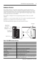
SLC 500 8-Point Analog Output Module 5 Hardware Features The module contains a removable terminal block, providing connection for 8 analog output channels, which are specifically designed to interface with analog current and voltage devices. The 1746-NO8I provides eight channels of current outputs, while the 1746-NO8V provides eight channels of voltage outputs. There are no input channels on the module. The module is configured via the programming software. There are no DIP switches.
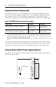
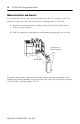
SLC 500 8-Point Analog Output Module Determining Power Requirements The module receives its power through the SLC 500 chassis backplane from the +5V dc/+24V dc chassis power supply. The +5V dc backplane supply powers the SLC circuitry, and the +24V dc backplane supply powers the module analog circuitry. The maximum current drawn by the module is shown in the table below.
SLC 500 8-Point Analog Output Module 7 • With the jumper in the 1-2 shorted position, the module draws all of its power from the backplane of the SLC system. • With the jumper in the 2-3 shorted position, the module draws its 24V dc power from the external power supply; however, the module still draws its 5V dc power from the backplane.
SLC 500 8-Point Analog Output Module Installation Install the SLC 500 system in a properly rated (i.e., NEMA) enclosure. Make sure that the SLC 500 system is properly grounded. Choosing a Slot in the Chassis Two factors determine where the analog module should be located in the chassis: ambient temperature and electrical noise. Consider the following conditions when selecting a slot for an analog module.
SLC 500 8-Point Analog Output Module 9 Remove Power ATTENTION ! Remove power before removing or installing this module. When you remove or install a module with power applied, an electrical arc may occur.
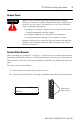
SLC 500 8-Point Analog Output Module Module Installation and Removal The module fits into any slot, except the processor slot (0), in either an SLC 500 modular system or an SLC 500 fixed system expansion chassis (1746-A2). 1. Align the circuit board of the analog module with the card guide of the chassis as shown below. 2. Slide the module in until both top and bottom retaining clips are secured.
SLC 500 8-Point Analog Output Module 11 Wiring Preliminary Considerations Use the following guidelines in planning the system wiring for the analog modules: ATTENTION ! Before wiring any analog module, disconnect power from the SLC 500 system and from any other source to the analog module. • Use Belden cable #8761 for wiring the analog modules making sure that the drain wire and foil shield are properly earth grounded. • Route the Belden cable separate from any other wiring.
SLC 500 8-Point Analog Output Module Wiring Procedure To wire your module, follow these steps: 1. Determine the length of cable you need to connect a channel to its field device. Remember to include additional cable to route the shield wire and foil shield to their ground points. 2. At each end of the cable, strip some casing to expose the individual wires. 3. Trim the exposed signal wires to 50 mm (2 in.) lengths. Strip about 5 mm (3/16 in.) of insulation away to expose the end of each wire. 4.
SLC 500 8-Point Analog Output Module 13 Terminal Block The 1746-NO8 module contains an 18-position, removable terminal block. The terminal pin-out is shown below. ATTENTION ! Disconnect power to the SLC before attempting to install, remove, or wire the removable terminal block. To avoid cracking the removable terminal block, alternate the removal of the slotted terminal block release screws.
SLC 500 8-Point Analog Output Module Configuration The module operates in Class 1 or Class 3 mode. This section describes how to configure the module for Class 1 operation. Class 1 provides basic data output with no user scaling. No configuration is required. This mode is compatible with the 1746-NO4 module. Class 3 allows you to select data formats, scale limits, ramping, clamping, alarming, safe state options and alarm latching.
SLC 500 8-Point Analog Output Module 15 Table 6 1746-NO8 Data Format Definitions for 1746-NO4 Data Format Selected Output Range Data Value (counts) Corresponding Signal Min. Max. Min. Max. ±10V dc 0 to 10V dc 0 to 5V dc 1 to 5V dc 0 to 20 mA 0 to 21 mA 4 to 20 mA -32768 0 0 +3277 0 0 +6242 +32764 +32764 +16384 +16384 +31208 +32764 +31208 -10V dc 0V dc 0V dc +1V dc 0 mA 0 mA 4 mA +10V dc +10V dc +5V dc +5V dc 20 mA 21 mA 20 mA 3.
SLC 500 8-Point Analog Output Module Specifications Table 7 General Specifications Specification 1746-NO8I 1746-NO8V I/O Chassis Location Any 1746 chassis slot except slot 0 Backplane Current Consumption (maximum) 120 mA at 5V dc 120 mA at 5V dc 250 mA at 24V dc (J4 jumper set to RACK) 0 mA at 24V dc (J4 jumper set to EXT) 160 mA at 24V dc (J4 jumper set to RACK) 0 mA at 24V dc (J4 jumper set to EXT) Backplane Power Consumption (typical) 5.6W Optional External 24V dc Power Supply N.E.C.
SLC 500 8-Point Analog Output Module 17 Table 8 Analog Output Specifications Specification 1746-NO8I 1746-NO8V Number of Outputs 8 8 Output Type Current Voltage Output Range 0 to 21.5 mA ±10.25V dc Output Coding (proportional scaling) 0 to 32,767 -32,768 to +32,767 Output D/A Converter Resolution 16-bit 366 nA/count 16-bit 320 µV/count Location of LSB in I/O Image Word 0000 0000 0000 0001 (for 1746-NO4 compatible data format; does not apply to other data formats) Non-Linearity 0.
SLC 500 8-Point Analog Output Module Table 9 Configuration and Status Specifications Specification 1746-NO8I 1746-NO8V Module ID Code Class 1: 3527 Class 3: 12727 Class 1: 3528 Class 3: 12728 Number of Output Channels 8 (selectable for each channel) Voltage Output Ranges 8 • • • • Current Output Ranges 4 to 20 mA 0 to 20 mA 0 to 21 mA 0 to 21.5 mA n/a • • • • • n/a (selectable for each channel) -10 to +10V dc -10.25 to +10.
SLC 500 8-Point Analog Output Module 19 Table 10 Environmental Specifications Specification 1746-NO8I Operating Temperature 0°C to +60°C (+32°F to +140°F) Storage Temperature -40°C to +85°C (-40°F to +185°F) Operating Humidity 5 to 95% non-condensing 1746-NO8V Vibration Operating: 5.0G at 10 to 500Hz, One Octave/min sweep, 10 sweeps Shock Operating: 30G (3 pulses, 11 ms) Non-Operating: 50G (3 pulses, 11 ms) Free Fall (drop test) Portable, 2.268 kg (5 lbs) or less at 0.762 m (30 in.
Rockwell Automation Support Rockwell Automation provides technical information on the web to assist you in using our products. At http://support.rockwellautomation.com, you can find technical manuals, a knowledge base of FAQs, technical and application notes, sample code and links to software service packs, and a MySupport feature that you can customize to make the best use of these tools.