Allen-Bradley Open-loop Velocity Control Module (Cat. No.
Important User Information Because of the variety of uses for the products described in this publication, those responsible for the application and use of this control equipment must satisfy themselves that all necessary steps have been taken to assure that each application and use meets all performance and safety requirements, including any applicable laws, regulations, codes and standards.
Manual Changes (Series A/D) Changes to this revision of the manual include these additions: • Considerations for Selecting the "15V dc Power Supply (chapter 4) • Other Design Considerations (chapter 4) • Testing for Proper System Operation (chapter 5) • Power Supply Loading Specifications (appendix A) Publication 1746-6.
toc–ii Summary of Changes Notes: Publication 1746-6.
Table of Contents System Overview . . . . . . . . . . . . . . . . . . . . . . . . . . . . . . . . 1–1 Chapter Objectives . . . . . . . . . . . . . . . . . . . . . . . . . . . . . . . . . . What Is the 1746-QV Module? . . . . . . . . . . . . . . . . . . . . . . . . . . What Is an SLC-500 System? . . . . . . . . . . . . . . . . . . . . . . . . . . Why Use This System? . . . . . . . . . . . . . . . . . . . . . . . . . . . . . . . How Does It Work? . . . . . . . . . . . . . . . . . . . . . . . . . . . . . .
ii Table of Contents Operating the Module for the First Time . . . . . . . . . . . . . . . 5–1 Chapter Objectives . . . . . . . . . . . . . . . . . . . . . . . . . . . . . . . . . . Power Up the System . . . . . . . . . . . . . . . . . . . . . . . . . . . . . . . . Check Wiring and Grounding . . . . . . . . . . . . . . . . . . . . . . . . . . Get Ready to Move the Ram . . . . . . . . . . . . . . . . . . . . . . . . . . . Move the Ram . . . . . . . . . . . . . . . . . . . . . . . . . . . . . . . . . . .
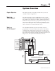
Chapter Objectives This chapter presents a conceptual overview of how you use the 1746-QV module in an application. What Is the 1746-QV Module? The 1746-QV module is part of an SLC-based open-loop control system for controlling the speed and placement of an hydraulic ram. The module accepts an input from a linear displacement transducer (LDT) and motion profiles that you program into the SLC processor, and varies its output in the range of "10V dc.
1–2 System Overview Why Use This System? Because you can change the speed of the hydraulic ram with extend and retract profiles and store additional profiles (recipes) in data table iNteger (N) files, this control system has these benefits: • reduced cycle time – you can increase ram speed for faster operation • reduced or eliminated pressure spikes and water-hammering for smoother operation and less wear and tear on the machine – you can profile accelerations and decelerations of the hydraulic ram • en
Use this chapter as an abbreviated procedure for getting the 1746-QV module into operation or as an overview if you need more information. Procedure 1. Load Ladder Logic into Your Computer Chapter 3 Obtain the ladder program (appendix B) from Rockwell Software Bulletin Board (BBS) or the Internet. From BBS: (216) 646-ROCK (-7625). If a new user, follow prompts to register. Log in. Look for 1746QV in the Allen-Bradley Products Library. The manual is in Word format.
2–2 Quick Start 4. Connect Module Output Terminals to Output Devices With Correct Bonding Important: Connect the shield of the amplifier output cable to a 0V connection in the amplifier. +24V dc PS 0V dc PS Servo Amplifier (Proportional) 0V 1746-QV Output Terminal Block 5. Analog Output ("10v dc) 2 1 (+) Diff.
Setting Up the Software Chapter Objectives This chapter helps you do the following: • Obtain the ladder program electronically • Configure your SLC processor off-line • Modify N files in your SLC processor, off-line • General conventions for profiles • Profile operation Obtaining the Ladder Program Electronically from BBS or the Internet You can obtain ladder logic electronically and download it to your SLC processor conveniently without the worry of data-entry errors.
3–2 Setting Up the Software 5. Download ladder program VELMOD (65 Kbyte SLC code) into the subdirectory on your hard drive where your programming software looks for files. With RSLogix: C:\ . . . RSLogix 500 English\Project. 6. Download the ladder program to your SLC processor. 7. Download the manual into a hard drive subdirectory. You must decompress the Word version with PKUNZIP available on BBS. To Access the Internet: 1. Access the Allen-Bradley webpage at: 2.
Setting Up the Software 3–3 5. Enter values in the G file: If the module was listed: If the module was not listed (you entered the ID): You get the G–file Setup screen. Enter data from the table, below. You get the following display, shown in decimal radix. Enter a value in each word as shown, next. G–file display for unlisted module (shown in decimal radix): Ge:0 2056 0 0 0 0 0 0 Enter a value at each G-file word address and press [ENTER]. Then cursor to the next word address and repeat.
3–4 Setting Up the Software Modify N Files in Your SLC Processor, Off-line One N file may contain the initial commands, setpoints, and values for configuring the extend and retract profiles.
Setting Up the Software General Conventions for Profiles 3–5 Consider the following when you set up your profiles: • Extend and retract define the profile with respect to the LDT head: extend is always away from the head, retract is always towards it • Position data changes direction depending on how you set configuration bit Ge:0/15 for LDT motion: 0 = position data increases when moving away from LDT head 1 = position data increases when moving towards LDT head • Each position setpoint triggers from t
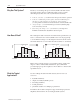
3–6 Setting Up the Software For Position Data Increasing Towards LDT Head (Ge:0/15 = 1) Voltage Output = 0 past position 1 Position V1 Speed Segment 6 V2 V3 V4 V5 V6 V7 Speed Speed Speed Speed Speed Segment 5 Segment 4 Segment 3 Segment 2 Segment 1 LDT head P1 P2 P3 P4 P5 P6 P7 • Starting with the ram between P7 and the LDT head (open position), running the extend profile results in V7 applied to the output. As the ram passes below P7, V6 is applied to the output, etc.
Setting Up the Hardware Chapter Objectives This chapter helps you install the hardware with these tasks: • • • • • Connect the LDT to Module Inputs connect the LDT to module input terminals connect module output terminals to output devices minimize interference from radiated electrical noise considerations for the "15V dc power supply other design considerations We assume that you will use one of the following types of LDT: • Temposonics II: RPM TTSRxxxxxxR, or DPM TTSRxxxxxxDExxx • Balluf
4–2 Setting Up the Hardware Connect Module Outputs to Output Devices Module outputs connect to a separate 2-conductor output terminal block located beneath the input terminal block. +24V dc PS 0V dc PS 1746-QV Output Terminal Block 2 1 Analog Output ("10v dc) Servo Amplifier (Proportional) (+) Diff. (–) Input 0V Outputs A to valves B Important: Ground the shield of the amplifier output cable to a 0V connection in the amplifier. Do not connect the shield to earth ground.
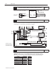
Setting Up the Hardware 4–3 • run shielded cables only in low-voltage conduit • place the SLC-500 processor, power supply, and I/O chassis assembly in a suitable enclosure Typical grounding and shielding for this type of control system: "15V Power Supply (+) (C) (–) 1746-QV Module Case GND 24V Power Supply (–) (+) Case GND Input LDT Power 1 2 3 LDT Signals 5-8 Belden 8770 Belden 8761 4 Analog Output Output 0V Belden 8761 Servo Proportional Amplifier Case GND Cable Note earth ground Piston-
4–4 Setting Up the Hardware Application of the "15V Power Supply The module uses the "15V dc power supply to drive the "10V dc valve output and to power the LDT. The module detects loss of "15V dc with its internal LDT diagnostic. The diagnostic concludes loss of "15V when it detects loss of LDT magnet. Partial failure of the "15V dc power supply may cause limited machine operation when the LDT continues to operate properly. Some LDTs will operate with its supply voltage down to 12V.
Operating the Module for the First Time Chapter Objectives This chapter outlines the steps for operating the module for the first time with an operating hydraulic ram. We cover these steps: • power-up the system • test for proper system operation • troubleshoot possible problems Power Up the System Starting with module and LDT power turned off, bring the system on-line for the first time as follows (refer to I/O wiring in chapter 4): Check Wiring and Grounding 1.
5–2 Operating the Module Get Ready to Move the Ram 1. Turn on the +24V dc PS that powers the amplifier. 2. Turn on the hydraulic pump and “null” the ram for no movement. 3. Turn off all power supplies. 4. Connect the LDT cable and input terminal block. 5. Turn on all power supplies. 6. Be sure that you have loaded the extend and retract profiles into the module. 7. Observe module LEDs. The RUN LED (green) should be blinking. If not blinking, refer to troubleshooting covered last in this chapter.
Operating the Module 5–3 2. After reversing the sign of voltages (if needed), run the extend profile again by changing the value in N7:50 to 1. Observe that the direction of ram travel is correct. Important: Reset the value in N7:50 to 0. 3. Check the position value reported in the status word, N7:61, as you run the ram to the end of its travel.
5–4 Operating the Module Test for Proper System Operation ATTENTION: Test for proper system operation to verify that precautions to guard against unexpected motion perform as intended. (See Power Supply and Design Considerations in chapter 4) Because of the wide variety of applications for this module, we leave the procedural details to you.
Operating the Module Bit #: 12 13 14 15 5–5 Description: (for error & fault bits 0-8, status of 0 = OK, status of 1 = fault.) The module sets this bit after it stores retract position setpoints or voltage values, or when retract profile is active. It remains set until another operation is performed. The module sets this bit after it stores your position setpoints. It resets it after you reset the “program position” bit (O:e.0/5 or O:e.0/7) The module sets this bit after it stores your voltage values.
5–6 Operating the Module Notes: Publication 1746-6.
Module Specifications This appendix lists the specifications for the 1746-QV Open-loop Velocity Control Module.
A–2 Module Specifications Notes: Publication 1746-6.
The following data define extend and retract profiles for the sample program: Extend position setpoints Extend voltage values Retract position setpoints Retract voltage values #N7:0 #N7:10 #N7:20 #N7:30 This ladder program loads profiles into the module through the output image table. (The 1746-QV module is in slot 1 for this example.) Rung 2.
B–2 Ladder Program Rung 2:5 | Set to |Extend |Run/store |Positions |Voltages | | program |profile |retract |stored |stored | | profile |complete Retract Velocity Setpts.| | | | N7:40 N7:8 I:1.0 I:1.0 I:1.0 +COP––––––––––––+ | |–––] [–––––––––] [–––––––] [––––––––] [––––––]/[––––––––––––+COPY FILE +–| | 0 0 12 13 14 |Source #N7:30| | | |Dest #O:1.
SLC Processor Files You use the following files when programming the SLC processor for an application with the 1746-QV module: • input image table to indicate status • G file to configure the module for its LDT • output image table for commands and loading profiles Input Image Table Word 0 (I:e.0 or N7:60 in the ladder program) reports status such as hardware faults, your data-entry errors, and acknowledgement of profile data stored in the module. Word 1 reports position data.
C–2 SLC Processor Files G File Use this file (Ge:0) to configure the module for use with the LDT. Example values are those from the sample ladder logic (appendix B). Word: Function of G-file Word: 0 Reserved. Do NOT use. Range: Description of G-file Word or Bit: Example: n/a The processor stores a code for the 1746-QV module. 2056 words 1 & 2 refer to the gradient or transducer calibration value stamped on the name plate on the transducer housing. For eexample: 8.
A I, J, K access to BBS or Internet, 3-1, 3-2 ID of module, 3-2, A-1 applications of module, 1-2 input terminal block, of module, 4-1, 5-1 input image table (status), 5-4, C-1 B Internet, access to, 3-2 BBS, Rockwell Software Bulletin Board, 3-1 benefits, of module, 1-2 bits command, 3-4, C-2 G-file configuration, 3-3, B-2, C-2 status, 5-4, C-1 C cables, 4-3 calibration (value) of LDT, 3-3, B-2, C-2 configure G file, 3-3, B-2, C-2 motion profiles, 1-2, 3-4 SLC processor, 3-2 connections, inpu
I–2 Q quick start, 2-1 R ram, hydraulic, 1-1, 1-2 procedure to move, 5-2, 5-3 set reference position of, 5-3 reference, preset, 3-3, 5-3 retract profile, 1-2, 3-4, 5-3 reverse motion, 5-2 S segments, speed, 1-2, 3-4, 3-5 (also see voltage values) shielding, of cables, 4-2, 4-3, 5-1 specifications, of module, A-1 status (input image table) 5-4, C-1 of outputs, 5-4 system, power up, 5-1 T, U, V testing, for proper system operation, 5-4 travel, length of LDT, 1-2, 3-3 troubleshooting, with LEDs, 5-2 module
Allen-Bradley, a Rockwell Automation Business, has been helping its customers improve productivity and quality for more than 90 years. We design, manufacture and support a broad range of automation products worldwide. They include logic processors, power and motion control devices, operator interfaces, sensors and a variety of software. Rockwell is one of the world’s leading technology companies. Worldwide representation.