User Manual SLC 500 EtherNet/IP Adapter Catalog Number 1747-AENTR
Important User Information Solid-state equipment has operational characteristics differing from those of electromechanical equipment. Safety Guidelines for the Application, Installation and Maintenance of Solid State Controls (publication SGI-1.1 available from your local Rockwell Automation sales office or online at http://www.rockwellautomation.com/literature/) describes some important differences between solid-state equipment and hard-wired electromechanical devices.
Preface Read this preface to familiarize yourself with the rest of the manual. It provides information concerning: • who should use this manual • the purpose of this manual • related documentation Who Should Use this Manual Use this manual if you are responsible for designing, installing, programming, or troubleshooting control systems that use the EtherNet/IP Adapter Module. You should have a basic understanding of electrical circuitry and familiarity with relay logic.
Preface Notes: iv Rockwell Automation Publication 1747-UM076C-EN-E - January 2013
Table of Contents Preface Who Should Use this Manual . . . . . . . . . . . . . . . . . . . . . . . . . . . . . . . . . . . . . . iii Purpose of this Manual . . . . . . . . . . . . . . . . . . . . . . . . . . . . . . . . . . . . . . . . . . . . iii Additional Resources . . . . . . . . . . . . . . . . . . . . . . . . . . . . . . . . . . . . . . . . . . . . . . iii Chapter 1 About the SLC 500 EtherNet/IP Adapter Overview . . . . . . . . . . . . . . . . . . . . . . . . . . . . . . . . . . . . . . . . . . . .
Table of Contents Chapter 5 Configure the Adapter for Direct Connection through the RSLogix 5000 or Logix Designer Software Overview . . . . . . . . . . . . . . . . . . . . . . . . . . . . . . . . . . . . . . . . . . . . . . . . . . . . . . . . Set Up the Hardware . . . . . . . . . . . . . . . . . . . . . . . . . . . . . . . . . . . . . . . . . . . . . Create the Example Application . . . . . . . . . . . . . . . . . . . . . . . . . . . . . . . . . . . Configure the I/O . . . . . . . . . . . . . . . . . .
Chapter 1 About the SLC 500 EtherNet/IP Adapter Overview Module Description This chapter provides an introduction to the features and functionalities of the 1747-AENTR SLC 500 EtherNet/IP Adapter. It includes the following sections.
Chapter 1 About the SLC 500 EtherNet/IP Adapter Connections can be made to support 1746 and 1747 analog, digital, and specialty I/O modules installed in the backplane. IMPORTANT Logix Designer application (previously RSLogix 5000) revision 21 and later, and firmware revision 2.001 and later supports: • multiple chassis, with a maximum number of three chassis; • a maximum of 30 SLC I/O modules; • a maximum of 96 Class 1 connections; • up to 8 Class 3 connections.
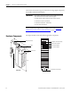
About the SLC 500 EtherNet/IP Adapter 45845 Chapter 1 45846 Right side view Left side view Ethernet connectors (RJ-45) 1 8 8 1 45844 Bottom view The 1747-AENTR in a Logix System In this example, the I/O modules communicate with the controller through the 1747-AENTR adapter. The controller can produce and consume tags to the I/O. Configuration of devices and the network is done through the personal computer running the controller and configuration software.
Chapter 1 About the SLC 500 EtherNet/IP Adapter Hardware/Software Compatibility Diagnostic Indicators 4 The adapter and the applications described in this manual is compatible with the following firmware revisions and software releases. Product Firmware Revision/ Software Release 1747-AENTR 1.001 or later Logix controller v20 or later RSLogix 5000 or Logix Designer v20 or later RSLinx software v2.
About the SLC 500 EtherNet/IP Adapter What the Adapter Does Chapter 1 The 1747-AENTR EtherNet/IP adapter performs the following primary tasks: • Control of real-time I/O data (also known as implicit messaging) – the adapter serves as a bridge between I/O modules and the network • Support of messaging data for configuration and programming information (also known as explicit messaging) CONTROLLER E N B T EtherNet/IP Network 1 7 4 7 A E N T R Use of the Common Industrial Protocol (CIP) SLC I/O Other
Chapter 1 About the SLC 500 EtherNet/IP Adapter input modules are not polled by a controller. Instead, they produce (multicast or unicast) their data periodically or at a cyclic rate. Unicast is the default for version 20 with multicast as a selectable option. The frequency of update depends upon the options chosen during configuration and where on the network the input module resides. The input module, therefore, is a producer of input data, and the controller is a consumer of the data.
Chapter 2 Install Your Adapter This chapter describes how to install the 1747-AENTR adapter and connect it to the EtherNet/IP network. The following table lists where to find specific information.
Chapter 2 Install Your Adapter The adapter’s subnet mask is 255.255.255.0 and the gateway address is set to 0.0.0.0. The adapter does not have a host name assigned, or use any Domain Name System when using the network address switch settings. If the switches are set to an invalid number (for example, 000 or a value greater than 254 excluding 888), the adapter checks to see if DHCP is enabled. Setting the switches to 888 restores default factory settings.
Install Your Adapter Chapter 2 Refer to the Industrial Controller Wiring and Grounding Guidelines publication 1770-4.1 for proper grounding and wiring methods to use when installing your module. 1. Remove power from the I/O chassis before inserting (or removing) the module. 2. Align the circuit board with the chassis card guide in the left slot. 3. Install the module in slot 0 of the chassis by aligning the circuit board with the chassis card guide.
Chapter 2 Install Your Adapter Wire the RJ-45 connectors as shown. Signal 1 TxData+ 2 TxData- 3 Recv Data+ 4 Reserved 5 Reserved 6 Recv Data- 7 Reserved 8 Reserved RJ-45 RJ-45 connectors 1 8 8 1 45844 1747-AENTR module bottom view To connect the module to the network, follow these steps: WARNING: If you connect or disconnect the communication cable with power applied to this module or any device on the network, an electrical arc can occur.
Install Your Adapter Chapter Summary Chapter 2 This chapter provided instructions on how to install and wire the module. It also included power requirements for the module.
Chapter 2 Install Your Adapter Notes: 12 Rockwell Automation Publication 1747-UM076C-EN-E - January 2013
Chapter 3 Configure the Adapter for Your EtherNet/IP Network Before using your adapter in an EtherNet/IP network, you need to configure it with an IP address, subnet mask, and optional Gateway address. This chapter describes these configuration requirements and the procedures for providing them. Here are ways you can do this: • Use the Rockwell Automation BootP/DHCP utility, version 2.3 or later, that ships with RSLogix 5000 or RSLinx software.
Chapter 3 Configure the Adapter for Your EtherNet/IP Network IP Address The IP address identifies each node on the IP network, or system of connected networks. Each TCP/IP node on a network, including the adapter, must have a unique IP address. The IP address is 32 bits long and has a Network ID part and Host ID part. Networks are classified A, B, C, or other. The class of the network determines how an IP address is formatted.
Configure the Adapter for Your EtherNet/IP Network Chapter 3 When a node needs to communicate with a node on another network, a gateway transfers the data between the two networks. The figure shows gateway G connecting Network 1 with Network 2. A 128.1.0.1 128.1.0.2 Network 1 G B C 128.2.0.1 128.2.0.2 128.2.0.3 Network 2 When host B with IP address 128.2.0.1 communicates with host C, it knows from C’s IP address that C is on the same network.
Chapter 3 Configure the Adapter for Your EtherNet/IP Network Two bits of the Class B host ID are used to extend the network ID. Each unique combination of bits in the part of the Host ID where subnet mask bits are 1 specifies a different physical network. The new configuration is: A 128.1.0.1 Network 1 128.1.0.2 G B C 128.2.64.1 128.2.64.3 128.2.64.2 Network 2.1 G2 D E 128.2.128.1 128.2.128.3 128.2.128.2 Network 2.2 A second network with Hosts D and E was added. Gateway G2 connects Network 2.
Configure the Adapter for Your EtherNet/IP Network Chapter 3 1. Run the BootP software. In the BOOTP Request History panel you see the hardware addresses of devices issuing BootP requests. 2. Double-click the hardware address of the device you want to configure. The New Entry dialog appears with the device’s Ethernet Address (MAC). 3. Enter the IP Address you want to assign to the device and click OK.
Chapter 3 Configure the Adapter for Your EtherNet/IP Network When the address displays in the IP Address column in the Request History section, the IP address assignment has been made. 4. To make this configuration static in the device, highlight the device in the Relation List panel, and click the Disable BOOTP/DHCP button. When power is cycled to the device, it uses the configuration saved in nonvolatile memory and will not issue a DHCP request. 5.
Configure the Adapter for Your EtherNet/IP Network Chapter 3 2. Select the folder where you want to save the Relation List. 3. Enter a File name for the Relation List, for example, control system configuration, and click Save. You can leave the Save as type at the default setting: Bootp Config Files (*.bpc). You now have the option to open the file containing the Relation List at a later session.
Chapter 3 Configure the Adapter for Your EtherNet/IP Network Notes: 20 Rockwell Automation Publication 1747-UM076C-EN-E - January 2013
Chapter 4 Plan to Use Your EtherNet/IP Adapter This chapter explains how the adapter operates on Ethernet and provides information to assist you in configuring your system.
Chapter 4 Plan to Use Your EtherNet/IP Adapter List of I/O Modules Supported by the 1747-AENTR Adapter Catalog Number Catalog Number Type 1746-IO12DC Digital Combination Module 1746-NO4I Analog Output Module 1746-ITB16 DC Digital Input Module 1746-NO4V Analog Output Module 1746-ITV16 DC Digital Input Module 1746-NR4 RTD/Resistance Input Module 1746-IV8 DC Digital Input Module 1746-NT4 Thermocouple/mV Input Module DC Digital Input Module 1746-NI16V(1) Analog Input Module DC Digital Inp
Plan to Use Your EtherNet/IP Adapter Chapter 4 List of I/O Modules NOT Supported by the 1747-AENTR Adapter Catalog Number 1747-BSN (2) Type Back-Up Remote I/O Scanner Module 1746-QV Open Loop Velocity Control Module 1746-BLM Blow Molding Module 1746-MPM Mold Pressure Module 1203-SM1(1) Scanport Module (Class 4 operation) (1) The module is not supported by the 1747-AENTR but appears in the RSLogix 5000 pick list (Select Module Type dialog).
Chapter 4 Plan to Use Your EtherNet/IP Adapter Communication between the 1747-AENTR module and the I/O modules is polled, similar to an SLC controller scan cycle. The adapter maintains a list of the module ID for each slot, and handles electronic key validation during connection requests, while processing ForwardOpen requests to the Connection Manager. Software Requirements RSLogix 5000 revision 20 or greater and RSLinx version 2.59 or greater are required to configure the 1747-AENTR adapter.
Plan to Use Your EtherNet/IP Adapter Chapter 4 different originators. The 1747-AENTR adapter supports up to five Listen Only connections per SLC module. IMPORTANT When a Listen Only connection is made, there must be an existing Exclusive Owner or Input Only connection, the connection RPIs must match exactly, the input chunk configuration (if any) must match exactly, and all connections to the same module must be Multicast.
Chapter 4 Plan to Use Your EtherNet/IP Adapter Chapter Summary 26 This chapter provided an overview of adapter operation on an EtherNet/IP network that can assist you in configuring your system.
Chapter 5 Configure the Adapter for Direct Connection through the RSLogix 5000 or Logix Designer Application Overview In the following example, a ControlLogix controller communicates with I/O modules through the adapter using a direct connection. The adapter makes a direct connection to each of the modules referenced by the data. The modules presented in this chapter use RSLogix 5000/Logix Designer application, revision 20 or later.
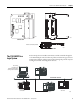
28 Configure the Adapter for Direct Connection through the RSLogix 5000 or Logix Designer Application To work along with this example, set up your system as shown in the figure. 1747-AENTR 10.88.70.2 Slot 0 1 2 3 Local chassis Data Slot Logix5575 controller (slot 1) 1746-BAS/B 0 1 2 3 1746-IA4 1756-EN2TR 10.88.70.4 (slot 3) 1746-IO8 Switch 10.88.70.26 Programming terminal 45176 • In the example application, we assume that the Logix5575 controller and 1756-EN2TR module (firmware revision 3.
Configure the Adapter for Direct Connection through the RSLogix 5000 or Logix Designer Application 29 2. From the File menu, select New. 3. The New Controller dialog opens. • Enter an appropriate Name for the Controller. • Select the correct Chassis Type, and Slot number of the Logix5575 controller, and the folder where you want to save the RSLogix 5000 file (Create In). The Description is optional. 4. Click OK.
30 Configure the Adapter for Direct Connection through the RSLogix 5000 or Logix Designer Application • Adding I/O modules as children of the 1747-AENTR adapter.. IMPORTANT Click the Help button on the configuration dialogs shown in this section if you need assistance in selecting and setting the parameters. Add the Local EtherNet/IP Bridge to the I/O Configuration 1. Right-click the I/O Configuration folder in the project dialog, and choose New Module from the dropdown list.
Configure the Adapter for Direct Connection through the RSLogix 5000 or Logix Designer Application 31 3. The New Module dialog opens. Configure your 1756-EN2TR EtherNet/IP Bridge module. You can configure the bridge module through the different tabs available. 4. Enter values for Name, IP Address, Slot, Electronic Keying, and Revision, noting that we used the following values: Name IP Address Slot Electronic Keying Revision EN2TR 10.88.70.4 3 Compatible Module 3.1 5.
32 Configure the Adapter for Direct Connection through the RSLogix 5000 or Logix Designer Application The Select Module Type dialog opens. 2. Choose 1747-AENTR. Click Create. 3. The Module Properties dialog opens. Specify the properties of the adapter. Note that for the purposes of illustration we have specified the following properties in the General tab of the New Module dialog. Name IP Address Slot 32 TEST_1747AENTR 10.88.70.
Configure the Adapter for Direct Connection through the RSLogix 5000 or Logix Designer Application 33 The Slot field appears grey because the slot is automatically 0 for the 1747-AENTR adapter. IMPORTANT 4. Click Change... The Module Definition dialog opens. 5. Choose values for Chassis Size, Electronic Keying and Revision, noting that we used the following values for our example: Connection Chassis Size Electronic Keying Revision IMPORTANT None (only choice available) 4 Compatible Module 1.
34 Configure the Adapter for Direct Connection through the RSLogix 5000 or Logix Designer Application In this example, you add a 1746-IO8 and a 1746-IA4 module with standard configurations. Use these steps as a guide when configuring different I/O modules for your system. TIP This example application uses I/O module default configurations. For more information, refer to the SLC 500 Systems Selection Guide, publication 1747-SG001. 1.
Configure the Adapter for Direct Connection through the RSLogix 5000 or Logix Designer Application 35 The New Module dialog opens. 3. Enter values for Name and Slot, noting that we used the following values. Name Slot TEST_1746IO8 1 4. Select the Connection tab. The RPI is selectable since it is a direct connection.
36 Configure the Adapter for Direct Connection through the RSLogix 5000 or Logix Designer Application 5. Enter 50 for requested packet interval (RPI) to set how often you exchange data with the I/O adapter. IMPORTANT TIP The default RPI of 20 ms is suitable for typical applications. Rockwell Automation recommends that you check or enable the option “Major Fault On Controller If Connection Fails While in Run Mode” on both the 1747-AENTR device and supported 1746 I/O modules. 6.
Configure the Adapter for Direct Connection through the RSLogix 5000 or Logix Designer Application 37 To add 1746-IA4 module to the project, follow the same procedure. After adding 1746-IA4, the I/O Configuration tree should appear as follows: Add Specialty I/O Modules using Advanced Connection The previous example illustrates how to add I/O modules that use Simple connection. This section shows how to add and configure a specialty I/O module with Advanced connection (in this example, 1746-BAS/B).
38 Configure the Adapter for Direct Connection through the RSLogix 5000 or Logix Designer Application 3. Enter a name for the device. Note that the following values are used in this example. Field Value Name TEST_1746BASB Revision 2.1 Electronic Keying Compatible Module (default) Connections Exclusive Owner – Advanced (default) 4. Click Change... on the General tab. On the Module Definition screen, configure data type as INT, Input Size = 72 (INTs), Output Size = 72 (INTs).
Configure the Adapter for Direct Connection through the RSLogix 5000 or Logix Designer Application 39 match the total size of all three Output Chunks. If the I/O sizes are larger than the chunk totals, the adapter will reject the connection request. If the chunk totals are larger than the I/O sizes, the adapter will accept the connection (but the backplane scan may waste cycles reading input data that will never be used). 5. Click OK on the Module Definition screen.
40 Configure the Adapter for Direct Connection through the RSLogix 5000 or Logix Designer Application 7. Click Configuration tab. The Chunk configuration determines the 1747-AENTR SLC backplane scan.
Configure the Adapter for Direct Connection through the RSLogix 5000 or Logix Designer Application 41 – Offset = 0 (starting INT offset in M1 File) • – – – Input Chunk 3 Size = 0 File = Offset = 0 8. Click OK to save the configuration. 9. On the Controller Organizer window, right-click Controller Tags under the Controller folder. Select Monitor Tags. 10. Examine the tags created for 1746-BAS/B. • TEST_1747AENTR:3:I.Data[0-7] represents Input File data (Input Chunk #1).
42 Configure the Adapter for Direct Connection through the RSLogix 5000 or Logix Designer Application After adding the 1746-BAS/B module, the I/O Configuration tree should appear as follows: Download the Program to the Controller Follow this procedure to download the program you just saved to the ControlLogix controller. 1. From the main menu, choose Communications>Who-Active. The Who Active dialog opens. 2. Navigate to select the slot where the controller is located in the chassis. 3.
Configure the Adapter for Direct Connection through the RSLogix 5000 or Logix Designer Application 43 • The mode changes to Remote Program prior to download. 5. On the Download dialog, choose Download. The RSLogix 5000/Studio 5000 software dialog opens. Notice that the 1756-EN2TR Bridge is now online. Custom Settings (Edit Adapter Configuration) You have now built the I/O Configuration tree in the RSLogix 5000 software.
44 Configure the Adapter for Direct Connection through the RSLogix 5000 or Logix Designer Application 1. In the Project dialog, right-click the 1747-AENTR adapter under I/O Configuration. 2. Select Properties. The following tabs are available for configuration. Tabs can be selected in any order. The following examples are for instructional purposes. 3. Click the Connection tab. Choose from the options in the Connection tab. Note that RPI is not applicable and is left blank.
Configure the Adapter for Direct Connection through the RSLogix 5000 or Logix Designer Application 45 4. To configure your IP settings, click the Internet Protocol tab. This tab is only available for editing when the device is online. To manually configure your IP settings, specify the IP address in the Physical Module IP Address field. 5. On the other fields (Domain Name, Host Name, Primary DNS Server Address, Secondary DNS Server Address), specify the corresponding parameter.
46 Configure the Adapter for Direct Connection through the RSLogix 5000 or Logix Designer Application To configure the ports: To Then Use the default port speed and duplex settings Leave Auto-negotiate port speed and duplex checked. This setting determines the actual speed and duplex setting. Manually configure your port’s speed and duplex settings Follow these steps. 1. Clear the Auto-negotiate port speed and duplex checkbox. 2. From the Current Port Speed pull-down menu, choose a port speed. 3.
Configure the Adapter for Direct Connection through the RSLogix 5000 or Logix Designer Application 47 1. On the I/O Configuration tree for your project in RSLogix 5000, right-click the name of your I/O module. 2. Select Properties. The Module Properties dialog appears and has the following tabs available for configuration. Note that for certain I/O modules, the Configuration tab may not be available. 3. Click Change...
48 Configure the Adapter for Direct Connection through the RSLogix 5000 or Logix Designer Application 1746-IO8 Module Definition shown Module Definition Fields Field Description Revision Specifies the major and minor module revision. Electronic Keying The electronic keying feature automatically compares the expected module, as shown in the RSLogix 5000 I/O Configuration tree, to the physical module before I/O communication begins.
Configure the Adapter for Direct Connection through the RSLogix 5000 or Logix Designer Application 49 Module Definition Fields Field Description Connections Defines the type of connection employed by the module.
50 Configure the Adapter for Direct Connection through the RSLogix 5000 or Logix Designer Application Connection Tab Fields Field Description Input type Defines the input type, whether unicast or multicast, for data sent over the network. The default input type is unicast. Unicast connections are point to point transmissions between a source node and destination node on the network. A Frame is sent to a single destination.
Configure the Adapter for Direct Connection through the RSLogix 5000 or Logix Designer Application 51 Chapter Summary This chapter provided instructions on how to configure the EtherNet/IP adapter for direct connection through the RSLogix 5000 software.
52 Configure the Adapter for Direct Connection through the RSLogix 5000 or Logix Designer Application Notes: 52 Rockwell Automation Publication 1747-UM076C-EN-E - January 2013
Chapter 6 Troubleshoot with the Status Indicators This chapter describes the different status indicators available in the 1747 EtherNet/IP Adapter and how to use them to troubleshoot the module. Interpret the Indicators The module has the folowing status indicators: • Module status indicator – indicates the state of the adapter. • Four-character dot matrix status display – works in conjunction with the Module status indicator to report normal operation and error conditions in your module.
Chapter 6 Troubleshoot with the Status Indicators Status Indicators Indicator State Description Module Off No power applied to device Green Device operating normally Flashing green Device has not been configured Flashing red Recoverable fault. • IP Address switches do not match configuration in use. • The device has completed a reset to factory default request because the switches were set to 888 at power up, and a power cycle is required. • The device is performing a firmware flash update.
Troubleshoot with the Status Indicators Chapter 6 Four-character Status Display MOD LED Display Description Probable Cause Recommended Action Flashing Red “OK” alternates with the message: “Factory Defaults Restored. Change Address Switches and Reset.” Factory defaults restored Node switches have been set to 888. The AENTR remains in this mode until the switches are changed. Power off the adapter. Remove the adapter from the chassis. Change the node address switch to something other than 888.
Chapter 6 Troubleshoot with the Status Indicators Four-character Status Display Chapter Summary 56 MOD LED Display Description Probable Cause Recommended Action Solid Red “0001” Fatal error The adapter has failed a hardware test, discovered too many racks (that is, greater than 3), or gone into a state from which it cannot recover. Verify the correct number of I/O racks and power cycle the adapter. Contact Technical Support if problem persists.
Appendix A Specifications The 1747-AENTR has the following specifications, ratings, and certifications.
Appendix A Specifications Environmental Specifications Attribute Value Relative humidity IEC 60068-2-30 (Test Db, Unpackaged Damp Heat): 5…95% noncondensing Vibration IEC 60068-2-6 (Test Fc, Operating): 2.
Appendix B Adapter Web Dialogs Overview Work with the Home Page The Web dialog of the I/O adapter offers extensive internal and network diagnostics. To view the Web dialogs, enter the IP address of the I/O adapters into your browser.
Appendix B Adapter Web Dialogs To display and work with the adapter diagnostics home page, follow these procedures. IMPORTANT Make sure that your PC Internet LAN setting and your TCP/IP settings are configured to access the subnet on which your adapter communicates. 1. From your web browser, enter the adapter IP address to see the Home page. Enter the adapter IP address to see the home page. 2. From the Home page, click Expand to show options, or minimize to see Diagnostics and Configuration.
Adapter Web Dialogs Appendix B Work with the Diagnostics Pages To work with the Diagnostics options, follow these procedures. 1. From the Home page, click Diagnostics or Expand to see the following diagnostics options from the panel at the left. • Diagnostic Overview • Network Settings • Ethernet Statistics • I/O Connections 2. In the Refresh Rate field, you can type a refresh rate, noting that the default rate is 15 seconds. 3.
Appendix B Adapter Web Dialogs 1. Click Diagnostic Overview from the tab at the top of the page or panel on the left. The Diagnostic Overview page opens. 2.
Adapter Web Dialogs Appendix B – – – • – • – – – – Conn Closes Close Errors Conn Timeout Module Settings Switches SLC Backplane Statistics I/O Errors I/O Scans Completed Maximum Scan Time Average Scan Time Use the Network Settings Page To use the Network Settings page for network related information, follow this procedure. 1. Click Network Settings tab at the top of the page or panel on the left. This opens the Network Settings page. 2.
Appendix B Adapter Web Dialogs – – – • – • – – – – – Default Domain Name Host Name Name Resolution Ethernet Interface Configuration How the Network Configuration was obtained - Static or Dynamic Ethernet Port 1 and 2 Interface State Link Status Media Speed Duplex Autonegotiate Status Use the Ethernet Statistics Page To use the Ethernet Statistics page for information about the Ethernet link and interface and media counters, use this procedure. 1.
Adapter Web Dialogs Appendix B 2.
Appendix B Adapter Web Dialogs 1. Click I/O Connections tab at the top of the page or panel on the left. The I/O Connections page opens. The top value in this column representing Lost shows the number of packets from the missing source. 2.
Adapter Web Dialogs Appendix B IMPORTANT If you set the value of the adapter switch to 888 and then power cycle the module, the following occurs: • The DHCP Enabled function is enabled (set to True). • The Ethernet link is negotiated automatically. The Auto Negotiate function is set to True. • The web server is enabled. The Disabled Web Server function is disabled. • The Ethernet port are disabled. Both ports are re-enabled once the switches are returned to their previous value and power is cycled.
Appendix B Adapter Web Dialogs • Identity • Network Configuration • Services Use the Device Identity Page To use the Device Identity page to make entries for the device name, device description, and device location, use this procedure. 1. Click Device Identity from the tab at the top of the page or panel on the left. The Identity page opens. 2.
Adapter Web Dialogs Appendix B 1. Click Network Configuration tab at the top of the page or panel on the left. The Network Configuration page opens. 2. From the Network Configuration page, complete these entries, noting that values for Network Interface are disabled when DHCP is Dynamic DHCP and port speed and duplex mode are disabled when Autonegotiate Speed and Duplex is selected.
Appendix B Adapter Web Dialogs • For Ethernet Link Port 1 and Port 2, specify the following: – Autonegotiate Status - Autonegotiate Speed and Duplex - Force Speed and Duplex – Select Port Speed – 10 megabits, 100 megabits – Select Duplex Mode – Half Duplex, Full Duplex 3. From the Network Configuration page, click Apply Changes to save the modified values.
Appendix C Configure the RSLinx Ethernet Communication Driver Overview To communicate with your adapter over your network, you must configure the RSLinx EtherNet/IP driver (AB-ETHIP). You can configure the AB_ETH driver with the IP addresses of all the Ethernet devices on your system. You need one of these drivers to download the example application programs in this manual. See the table for a list of the contents of this appendix.
Appendix C Configure the RSLinx Ethernet Communication Driver 2. From the Communications menu, select Configure Drivers. 3. Select EtherNet/IP Devices from the list and click Add/New... The Configure Dialog box opens. Make sure the Browse Local Subnet button is selected. The RSLinx software browses your local subnet and automatically reads the IP address.
Configure the RSLinx Ethernet Communication Driver Appendix C 4. Click OK. The AB-ETHIP driver is now configured and appears in the configured drivers window. 5. Close the RSLinx software.
Appendix C Configure the RSLinx Ethernet Communication Driver Notes: 74 Rockwell Automation Publication 1747-UM076C-EN-E - January 2013
Index Numerics 1746-BAS/B 25, 35 1746-IA4 25 1746-IO8 25 1746-RM001 35 1746-UM004 35 1747-AENTR 21 configuration 25 connect through RJ-45 9 custom settings 41 drawing 2 installation 7 ratings 55 specifications 55 status indicators 51 1756-EN2TR 25, 26 A adapter 21 configure 25 mounting 25 operation 21 additional resources iii auto negotiate 8, 57 B backplane 1, 8, 21, 38 BootP/DHCP 7, 11 relation List 16 connection 22, 25 advanced 35 direct 21, 25 maximum 21 simple 35 controller 26 ControlLogix 25 Logix
indicator diagnostic 3 Link 1 status 2, 51 Link 2 status 2, 51 status 2, 51 troubleshoot with 51 inhibit module 42 Input Only 22 installation 7 IP address 11, 12, 26, 58 isolation voltage 55 wire 10 RPI 5, 33, 34, 37 default value 34 RSLinx 3, 11, 22, 26 configure Ethernet driver 69 install 69 RSLogix 5000 3, 11, 14, 22, 25, 41, 44 connection properties 37 custom settings for I/O modules 44 Module Definition 36 S L latch 2 Listen Only 22 Literature Library 35 Logix system 3 M master and slave 4 media spe
Rockwell Automation Publication 1747-UM076C-EN-E - January 2013 77
Rockwell Automation Support Rockwell Automation provides technical information on the Web to assist you in using its products. At http://www.rockwellautomation.com/support/, you can find technical manuals, a knowledge base of FAQs, technical and application notes, sample code and links to software service packs, and a MySupport feature that you can customize to make the best use of these tools.