Backup Scanner Module Catalog Number 1747-BSN Installation Instructions Publication 1747-5.
Backup Scanner Module Important User Information Because of the variety of uses for the products described in this publication, those responsible for the application and use of this control equipment must satisfy themselves that all necessary steps have been taken to assure that each application and use meets all performance and safety requirements, including any applicable laws, regulations, codes and standards.
Backup Scanner Module 3 For More Information As part of our effort to preserve, protect, and improve our environment, Allen-Bradley is reducing the amount of paper we use. Less paper means more options for you. In addition to traditional printed publications and CD-ROM versions, we now offer on-line materials with the most up-to-date information you can get. We recommend that you read the related publications listed below before starting up your control system.
Backup Scanner Module Safety Considerations This equipment is UL certified for ordinary locations only. The module is C-UL certified for use in Class I, Division 2, Groups A, B, C, D, or nonhazardous locations only. The following attention statement applies to use in hazardous locations. ATTENTION: Explosion Hazard ! • Substitution of components may impair suitability for Class I, Division 2.
Backup Scanner Module 5 Overview The 1747-BSN Backup Scanner Module provides a high-speed communication channel between two modular SLC 500™ (5/02 or higher) processors. The 1747BSN backup system uses a set of modules, with one or more 1747-BSN modules residing in the primary system and one or more complementary modules in the secondary or backup system.
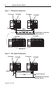
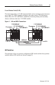
Backup Scanner Module Figure 1 RIO System Configuration Processor Processor 1747-BSN RS232 1747-BSN HSSL Remote I/O RS232/DH485 to Operator Interface Device 1747-ASB 1747-ASB Remote I/O Figure 2 DH+ System Configuration Processor Processor 1747-BSN 1747-BSN HSSL RS232 DH+ DH+ To DH+ Network RS232/DH485 to Operator Interface Device Publication 1747-5.
Backup Scanner Module 7 The 1747-BSN module provides backup functionality for the following: • DH+ or RIO on a single pair of modules - Both may be backed up when two or more pairs of modules are used. • RS232 - Any RS232 device communicating with channel 0 of the SLC controller may be backed up provided hardware-handshake lines are not required. These ports only allow switchover of the transmit, receive and ground wires for RS232.
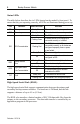
Backup Scanner Module Status LEDs The table below describes the six LEDs located on the module’s front panel. To ensure that they are operating correctly, all LEDs are illuminated during power-up. LED Definition Status and Color Indication PRI Primary Steady Green The module is in the primary mode. SEC Secondary Steady Amber The module is in the secondary mode. Steady Green The RIO link is working properly.
Backup Scanner Module 9 Local Status Link (LSL) The local status link is a 57.6K baud serial link used to exchange status between up to eight 1747-BSN modules residing in the same chassis. The illustration below shows the LSL and HSSL connections between primary and secondary chassis with more than one 1747-BSN module.
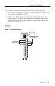
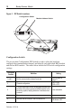
Figure 5 Backup Scanner Module DIP Switch Locations Configuration Switch Module Address Switch O N 1 2 3 4 5 6 1 2 3 4 O N 1 2 3 4 5 6 1 2 3 4 Configuration Switch The six-position Configuration DIP Switch is used to select the baud rate, configure the communication channel, and identify each individual BSN module and the last BSN module. The tables below define the DIP switch configuration settings. DIP Switch Position Definition Setting 1 and 2 Set the communication channel baud rate.
Backup Scanner Module 11 Baud Rate Settings Position 1 Position 2 Baud Rate ON ON OFF OFF ON OFF ON OFF 57.6K 115.2K 230.4K Disabled Module Address Switch The four-position Module Address DIP switch configures the BSN address in the LSL. The table below shows the address that corresponds to each setting. Switch Position Note: 1 2 3 OFF ON OFF ON OFF ON OFF ON OFF OFF ON ON OFF OFF ON ON OFF OFF OFF OFF ON ON ON ON 1747-BSN Address 1 2 3 4 5 6 7 8 Switch position 4 is not used.
Backup Scanner Module Switchover Conditions The 1747-BSN module transfers control from the primary to the secondary processor (switchover) if one of the following fault conditions occurs in the primary system: • power failure • major fault in the processor • 1747-BSN module fault • primary processor mode change from Run to Program Note: In order for switchover to occur, both primary and secondary modules must be working without faults prior to the event that triggers the switchover.
Backup Scanner Module 13 Inserting the Module into the Chassis 1. Disconnect power. 2. Align the full-sized circuit board with the chassis card guides of the leftmost slot of the first I/O module group in the I/O chassis. The first slot of the chassis is reserved for the processor. 3. Slide the module into the chassis until the top and bottom latches catch.
Backup Scanner Module Figure 7 Terminal Pinout LSL (Line 1 – Blue) LSL (Shield) LSL (Line 2 – Clear) 232 / 485 (A) to CPU 232 / 485 (B) to CPU 232 / 485 (COM) to CPU DH+ (Line 1) to CPU DH+ (Shield) to CPU DH+ (Line 2) to CPU Release Screw HSSL (Line 1 – Blue) HSSL (Shield) HSSL (Line 2 – Clear) 232 / 485 (A) to Link 232 / 485 (B) to Link 232 / 485 (COM) to Link RIO / DH+ (Line 1) to Link RIO / DH+ (Shield) to Link RIO / DH+ (Line 2) to Link Release Screw Use Belden™ 9463 cable when wiring the mod
Backup Scanner Module 15 HSSL Wiring Connect the HSSL to establish communication between the primary and secondary systems. Maximum cable length for the HSSL is 4.5 m (15 ft.). Local Status Link Wiring If you have more than one 1747-BSN module in the chassis, connect the LSL in series between modules in the same chassis. This enables BSN modules in the same chassis to exchange status information in order to perform switchovers in unison.
Specifications Operating Specifications Backplane Current Consumption 800 mA at 5V Operating Temperature +32°F to +140°F (0°C to +60°C) Storage Temperature -40°F to +185°F (-40C to +85°C) Humidity 5 to 95% without condensation Noise Immunity NEMA Standard ICS 2-230 Agency Certification (when product or packaging is marked) UL listed C-UL listed – Class I, Division 2, Groups A, B, C, D Temp.