
User Manual

10 Backup Scanner Module
Publication 1747-5.38
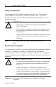
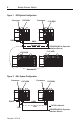
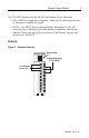
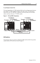
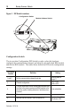
Figure 5 DIP Switch Locations
Configuration Switch
The six-position Configuration DIP Switch is used to select the baud rate,
configure the communication channel, and identify each individual BSN module
and the last BSN module. The tables below define the DIP switch configuration
settings.
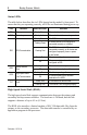
DIP Switch
Position
Definition Setting
1 and 2 Set the communication channel baud rate.
see the table on
page 11
3 Channel configuration.
DH+ = ON
RIO = OFF
4
This user identification switch differentiates between BSN
modules in the primary system and BSN modules in the
secondary system, helping determine if switchover has
occurred.
User selectable
5 Reserved.
6 Identifies the last module in the local status link.
Last module = ON
All others = OFF
12 34
O
N
12 3456
O
N
12 3
4
123456
Configuration Switch
Module Address Switch