
User Manual

Backup Scanner Module 13
Publication 1747-5.38
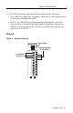
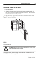
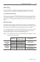
Inserting the Module into the Chassis
1.
Disconnect power.
2.
Align the full-sized circuit board with the chassis card guides of the left-
most slot of the first I/O module group in the I/O chassis. The first slot of
the chassis is reserved for the processor.
3.
Slide the module into the chassis until the top and bottom latches catch.
Figure 6 Inserting the Module
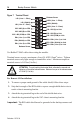
Wiring
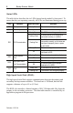
Terminal Wiring
The backup scanner module contains a green removable terminal block. The
terminal pinout is shown on page 14.
!
ATTENTION:
Disconnect power to the SLC before attempting to install, remove
or wire the removable terminal wiring block.