
User Manual

Backup Scanner Module 15
Publication 1747-5.38
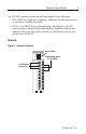
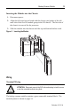
HSSL Wiring
Connect the HSSL to establish communication between the primary and
secondary systems. Maximum cable length for the HSSL is 4.5 m (15 ft.).
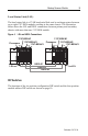
Local Status Link Wiring
If you have more than one 1747-BSN module in the chassis, connect the LSL in
series between modules in the same chassis. This enables BSN modules in the
same chassis to exchange status information in order to perform switchovers in
unison.
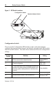
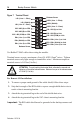
RIO Link Wiring
The backup scanner module is connected to other devices on the RIO link in a
daisy-chain (serial) configuration. There are no restrictions governing the space
between devices, provided the maximum cable distance is not exceeded.
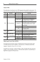
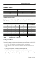
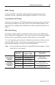
A ½ watt terminating resistor must be attached across lines one and two at each
end of the RIO link. The value of the resistor depends on the baud rate and
extended node capability, as shown in the table that follows.
Note:
To use extended node, all devices on the RIO link must support it. Refer
to each device’s user manual.
Baud Rate
Max. Cable Distance
(Belden™ 9463)
Resistor Size
Using
Extended Node
Capability
57.6K baud 3048 m (10,000 ft.)
82
Ω
1/2 Watt
Gray-Red-Black-Gold
115.2K baud 1524 m (5,000 ft.)
230.4K baud 762 m (2,500 ft.)
Not Using
Extended Node
Capability
57.6K baud 3048 m (10,000 ft.)
150
Ω
1/2 Watt
Brown-Green-Brown-Gold
115.2K baud 1524 m (5,000 ft.)
230.4K baud 762 m (2,500 ft.)
82
Ω
1/2 Watt
Gray-Red-Black-Gold