
User Manual
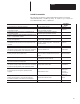
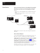
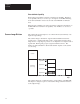
Table Of Contents
- 1747-6.8, Direct Communication Module User Manual
- Important User Information
- Summary of Changes
- Table of Contents
- Preface
- 1 - Overview
- 2 - Quick Start for Experienced Users
- 3 - Addressing
- 4 - Module Configuration
- 5 - Installation and Wiring
- 6 - Programming
- 7 - Troubleshooting
- 8 - Application Examples
- A - Specifications
- B - DCM Addressing Worksheet
- Index
- Back Cover
1
Chapter
1–1
Overview
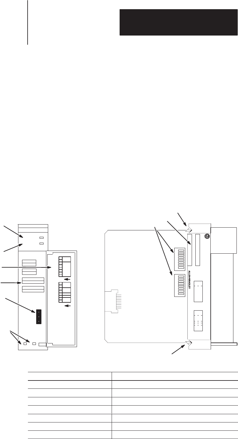
This chapter provides a hardware and system overview including physical
features and connectivity illustrations. It also explains data exchange
between processors and discusses rack size. Topics include:
• hardware overview
• system overview
• scanner image division
• communications flow
The Direct Communication Module, Catalog Number 1747–DCM, is used to
connect an SLC 500 Fixed Programmable Controller with expansion chassis
or any SLC 500 Modular Programmable Controller to a supervisory
Allen–Bradley Programmable Controller via the RIO Link, thereby
providing a distributed processing system. The DCM occupies one slot in
any SLC 500 chassis.
Cable Tie Slots
SLC 500
CAT
SERIAL NO.
DCM
FAULT LED
(Red)
Front Label
DIP Switches
RIO Link Connector
Self–Locking Tab
COMM LED
(Green)
DIRECT COMMUNICATION
MADE IN USA
COMM
FAULT
CONFIGURATION
RACK SIZE
1/4 1/2 3/4 1
RACK ADDR
FIRST I/O GROUP
0 2 4 6
DATA RATE (K B/S)
57.6 115.2 230.4
LINE 1 _______
SHIELD ______
LINE 2 _______
MODULE
8
7
6
5
4
3
2
1
8
7
6
5
4
3
2
1
I/O
GROUP
(LSB)
(MSB)
X
X
RACK
SIZE
LAST
RACK
CLR ON FL
T
DATA
RATE
SW 2
SW 1
Side Label
SW1 SW2
1
2345678
1
2345678
RACK
ADDR
1747–DCM
Door Label
Self–Locking Tab
SW2
SW1
O
N
1
2345678
O
N
1
2345678
I/O
GROUP
(LSB)
RACK
ADDRESS
(MSB)
RACK
SIZE
DATA
RATE
X
X
LAST
RACK
CLR ON FL
T
Hardware Features
Hardware
Function
FAULT LED Displays operating status
COMM LED Displays communication status
Front, Side and Door Labels Provide module configuration information
RIO Link Connector Provides physical connection to RIO network
Cable Tie Slots Secure and route wiring from module
DIP Switches Establish configuration parameters for the module
Self–Locking Tabs Secure module in chassis slot
H
ar
dw
are
O
v
er
vi
e
w