
User Manual
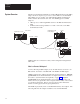
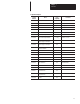
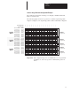
Table Of Contents
- 1747-6.8, Direct Communication Module User Manual
- Important User Information
- Summary of Changes
- Table of Contents
- Preface
- 1 - Overview
- 2 - Quick Start for Experienced Users
- 3 - Addressing
- 4 - Module Configuration
- 5 - Installation and Wiring
- 6 - Programming
- 7 - Troubleshooting
- 8 - Application Examples
- A - Specifications
- B - DCM Addressing Worksheet
- Index
- Back Cover
Chapter 1
Overview
1–5
Scanner Image Division Configuration Example
The example presented here can help you configure your RIO architecture.
Refer to it as necessary.
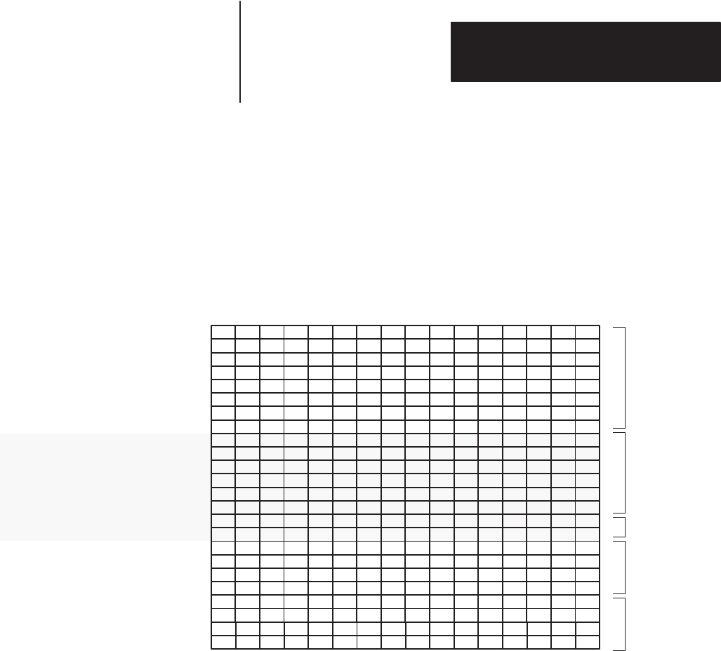
The following figure shows how a portion of a scanner’s input image table
might be configured. An output image table would be identically configured.
Rack 1 Group 2
Rack 1 Group 3
Rack 1 Group 0
Rack 1 Group 1
Rack 1 Group 6
Rack 1 Group 4
Rack 1 Group 5
Rack 0 Group 6
Rack 0 Group 7
Rack 0 Group 4
Rack 0 Group 5
Rack 0 Group 2
Rack 0 Group 3
0123456789101112131415
Decimal Bit Number
Word 0
Word 1
Word 2
Word 3
Word 4
Word 7
Word 8
Word 9
Word 10
Word 11
Word 12
Word 13
Word 14
Word 5
Word 6
Rack 0 Group 0
Rack 0 Group 1
Rack 2 Group 7
Rack 2 Group 5
Rack 2 Group 6
Rack 2 Group 3
Rack 2 Group 4
Rack 2 Group 1
Rack 2 Group 2
Word 15
Word 16
Word 17
Word 18
Word 19
Word 22
Word 23
Word 20
Word 21
Rack 1 Group 7
Rack 2 Group 0
Logical
Rack
0
Device
1
Device 2
Device 3
Logical
Rack
1
Logical
Rack 2
(Full logical rack)
(3/4 logical rack)
(1/2 logical rack)
Device
5
(1/2 logical rack)
Device
4
(1/4 logical rack)
012345671011121314151617
Octal Bit Number
Important: The configured image size of a DCM cannot cross logical rack
boundaries; it cannot use a portion of rack 0 and a portion of
rack 1.