
User Manual
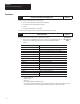
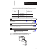
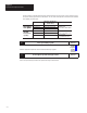
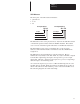
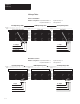
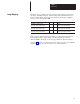
Table Of Contents
- 1747-6.8, Direct Communication Module User Manual
- Important User Information
- Summary of Changes
- Table of Contents
- Preface
- 1 - Overview
- 2 - Quick Start for Experienced Users
- 3 - Addressing
- 4 - Module Configuration
- 5 - Installation and Wiring
- 6 - Programming
- 7 - Troubleshooting
- 8 - Application Examples
- A - Specifications
- B - DCM Addressing Worksheet
- Index
- Back Cover
Chapter 2
Quick Start for Experienced Users
2–3
• the maximum number of physical devices and logical racks your scanner supports.
• the logical rack size of each DCM. This depends on how many I/O data words you need to transfer. The first word
is always the status word. The table below shows the number of data words transferred relative to the rack size.
If you configure the DCM as:
Then: Including the Status Word
1/4 Rack
1 data word (16 bits of I/O
data) are transferred.
Total transfer = 2 words
1/2 Rack
3 data words (48 bits of I/O
data) are transferred.
Total transfer = 4 words
3/4 Rack
5 data words (80 bits of I/O
data) are transferred.
Total transfer = 6 words
Full Rack
7 data words (112 bits of I/O
data) are transferred.
Total transfer = 8 words
3.
Choose
the type of slot addressing you will use.
Reference
Select DCM addressing. (A configuration worksheet is included in appendix B to assist you in DCM
image table addressing.)
Chapter 3
(Addressing)
Appendix B
(DCM Worksheet)
4.
Configure
the module using the DIP switches.
Reference
Configure your system by setting the DIP switches.
Chapter 4
(Module
Configuration)
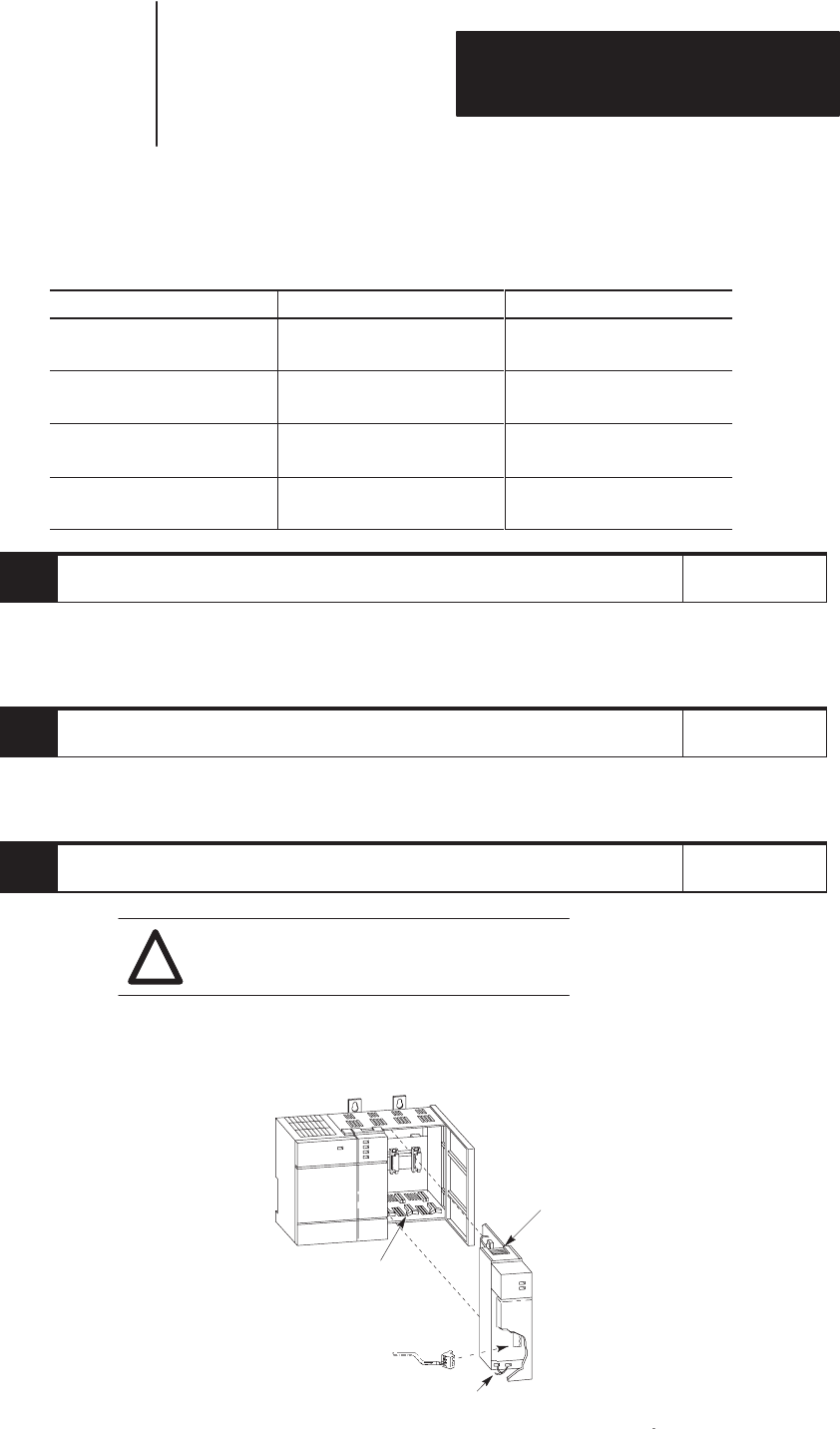
5.
Insert
the 1747-DCM module into the chassis.
Reference
ATTENTION: Never install, remove, or wire
modules with power applied to the chassis or
devices wired to the module.
!
Chapter 5
(Installation and
Wiring)
Review
SLC/DCM power requirements to ensure your SLC power supply has adequate reserve power
.
Make sure system power is off; then insert the DCM into your 1746 chassis. In this example
procedure, local slot 1 is selected.
.
.
.
Card Guide
Cable Tie
Module Release