
User Manual
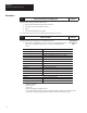
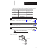
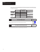
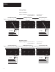
Table Of Contents
- 1747-6.8, Direct Communication Module User Manual
- Important User Information
- Summary of Changes
- Table of Contents
- Preface
- 1 - Overview
- 2 - Quick Start for Experienced Users
- 3 - Addressing
- 4 - Module Configuration
- 5 - Installation and Wiring
- 6 - Programming
- 7 - Troubleshooting
- 8 - Application Examples
- A - Specifications
- B - DCM Addressing Worksheet
- Index
- Back Cover
Chapter 2
Quick Start for Experienced Users
2–4
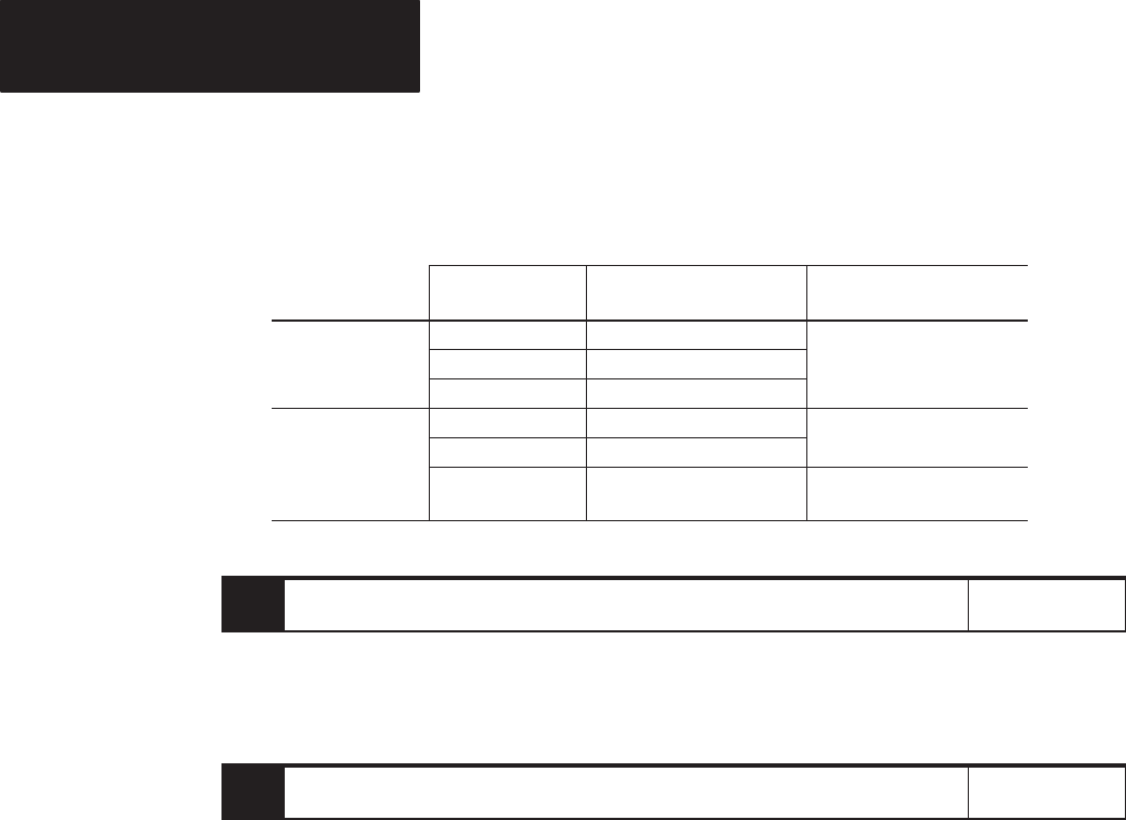
To wire the network, a 1/2 watt terminating resistor must be attached across line 1 and line 2 of the connectors at each
end (scanner and last physical device) of the network. The size of the resistor depends on the baud rate and extended
node capability, as shown below:
Baud Rate
Maximum Cable Distance
(Belden 9463)
Resistor Size
Us n xten e
57.6K baud 3048 meters (10,000 feet)
8 W 1
Us
i
n
g E
xten
d
e
d
o e apab l t
115.2K baud 1524 meters (5,000 feet)
8
2W
1
/2 Watt
rGr rG
N
o
d
e
C
apab
i
l
i
t
y
230.4K baud
762 meters (2,500 feet)
B
r
own–
Gr
een–B
r
own–
G
old
ot Us n
57.6K baud 3048 meters (10,000 feet)
1
50W
1
/2 Watt
N
ot
Us
i
n
g
xten e o e
115.2K baud 1524 meters (5,000 feet)
1
50
W
1
/2 Watt
Brown–Green–Brown–Gold
E
xten
d
e
d N
o
d
e
Capability
230.4K baud 762 meters (2,500 feet)
82W 1/2 Watt
Gray–Red–Black–Gold
6.
Enter
your ladder program.
Reference
Define the application requirements. Write and enter the ladder logic program.
Chapter 6
(Programming)
Chapter 8
(Application
Examples)
7.
Go
through the system start-up procedure.
Reference
Power up your system by performing standard start-up procedures as indicated in your processor
manual. No special start-up procedures are required when using the DCM module.
–