
User Manual
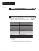
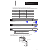
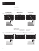
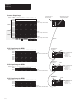
Table Of Contents
- 1747-6.8, Direct Communication Module User Manual
- Important User Information
- Summary of Changes
- Table of Contents
- Preface
- 1 - Overview
- 2 - Quick Start for Experienced Users
- 3 - Addressing
- 4 - Module Configuration
- 5 - Installation and Wiring
- 6 - Programming
- 7 - Troubleshooting
- 8 - Application Examples
- A - Specifications
- B - DCM Addressing Worksheet
- Index
- Back Cover
Chapter 3
Addressing
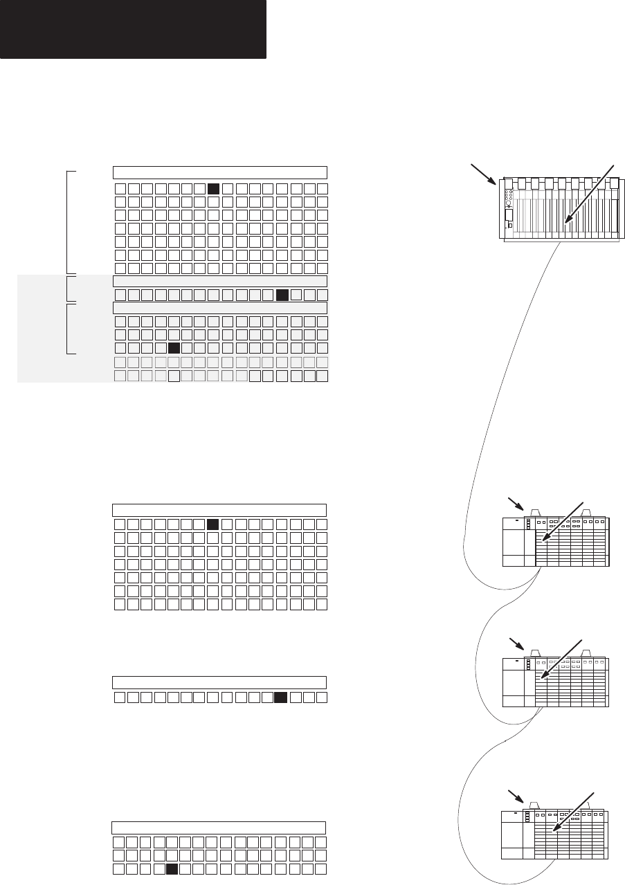
3–6
10 9
Word
2
Word 3
Word 4
Word 5
Word 6
Word 7
Octal 15 14 13 12 11 10 7 6 5 4 3 2 1 0
Group 0
Group 1
Group 0
Group 1
17 16
DCM
1
DCM 2
DCM 3
Module 2 Configured As:
Rack Address 2
I/O Group
0
Slot Number 1
Rack Size 1/4
Module 1 Configured As:
Rack Address 1
I/O Group
0
Slot Number 1
Rack Size Full
Module 3 Configured As:
Rack Address 2
I/O Group
2
Slot Number 2
Rack Size 1/2
Supervisory SLC or PLC
Remote I/O Scanner
DCM 1
Word 0
Word 1
Reserved for Status W
ord
Group 2
Group 3
Group 4
Group 5
Group 6
Group 7
Group 2
Group 3
Group 4
Group 5
15 14 13 12 11 10 7 6 5 4 3 2 1 098
Reserved for Status W
ord
Bit
Number: Decimal
Word
0
Word 1
15 14 13 12 11 10 7 6 5 4 3 2 1 098
Word 0
Word 1
Word 2
Word 3
Bit
Number: Decimal
15 14 13 12 11 10 7 6 5 4 3 2 1 098
I:1.1/8
(Slot
1, Word 1, Bit 8 Decimal)
I:1.1/3
(Slot 1, Word 1, Bit 3 Decimal)
O:021/2
(Rack 2, Group 1, Bit 3 Octal)
O:011/10
(Rack 1, Group 1, Bit 10 Octal)
O:025/13
(Rack 2, Group 5, Bit 13 Octal)
I:1.3/11
(Slot 2, W
ord 3, Bit 1
1 Decimal)
Bit
Number: Decimal
Scanner Output Image
SLC 1 Input Image for DCM 1
SLC 2 Input Image for DCM 2
SLC 3 Input Image for DCM 3
Group
6
Group 7
Reserved for Status W
ord
Reserved for Status W
ord
Reserved for Status W
ord
Reserved for Status W
ord
Reserved for Status W
ord
DCM 2
DCM 3
Supervisory SLC or
PLC Processor
RIO Link
Distributed SLC
Processor 2
Distributed SLC
Processor 1
Distributed SLC
Processor 3
13 12 11 8 7 6 5 4 3 2 1 015 14Decimal
Bit
Number: