
User Manual
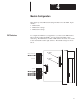
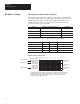

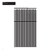

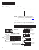

Table Of Contents
- 1747-6.8, Direct Communication Module User Manual
- Important User Information
- Summary of Changes
- Table of Contents
- Preface
- 1 - Overview
- 2 - Quick Start for Experienced Users
- 3 - Addressing
- 4 - Module Configuration
- 5 - Installation and Wiring
- 6 - Programming
- 7 - Troubleshooting
- 8 - Application Examples
- A - Specifications
- B - DCM Addressing Worksheet
- Index
- Back Cover
4
Chapter
4–1
Module Configuration
This chapter provides DIP switch setting information for the DCM. Topics
include:
• DIP switches
• DIP switch 1 settings
• DIP switch 2 settings
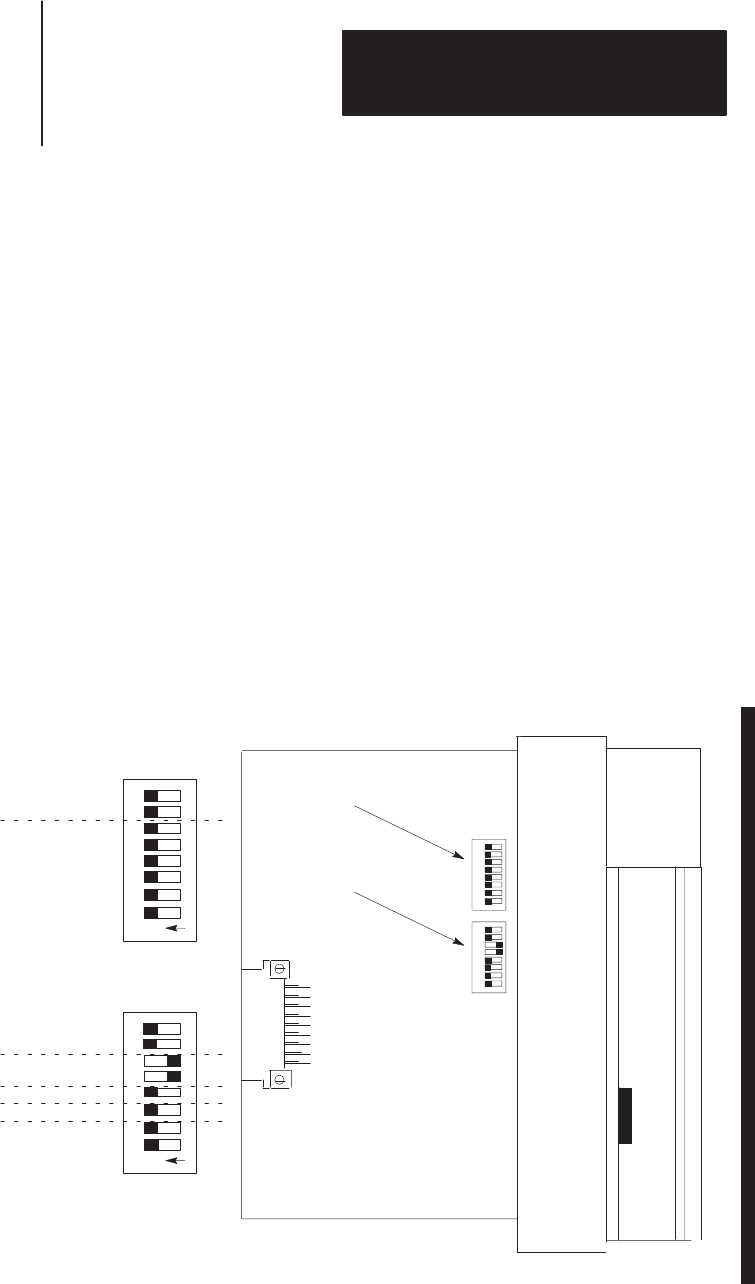
To configure the DCM for your application, you must set the DIP switches.
These switches enable the DCM to properly interpret the RIO system
addressing. The DCM has two banks of DIP switches mounted on its circuit
board. Each bank contains eight switches. The default settings are shown
below.
SW1
DIP
Switch 1
(SW1)
SW2
DIP Switch 2
(SW2)
Reserved
Rack
Size
Last Rack
Clear On Fault
8
O
N
1234567
SW1
Starting I/O Group Number
Rack Address
O
N
SW2
Data Rate
1
2345678
8
1234567
1
2345678
DIP Switches