
User Manual
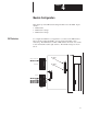
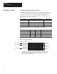


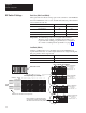

Table Of Contents
- 1747-6.8, Direct Communication Module User Manual
- Important User Information
- Summary of Changes
- Table of Contents
- Preface
- 1 - Overview
- 2 - Quick Start for Experienced Users
- 3 - Addressing
- 4 - Module Configuration
- 5 - Installation and Wiring
- 6 - Programming
- 7 - Troubleshooting
- 8 - Application Examples
- A - Specifications
- B - DCM Addressing Worksheet
- Index
- Back Cover
Chapter 4
Module Configuration
4–6
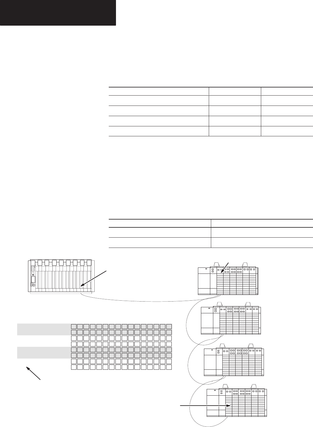
Rack Size (SW2-5 and SW2-6)
The logical rack size allocates image space in the scanner for each DCMs I/O
data. The DCM allows 1/4, 1/2, 3/4, and full rack addressing. SW2 switches
5 and 6 define the rack size.
Rack Size SW2-5 SW2-6
1/4 Logical Rack ON ON
1/2 Logical Rack ON OFF
3/4 Logical Rack OFF ON
Full Logical Rack OFF OFF
Important: The DCM image cannot cross logical rack boundaries.
Therefore, as an example, configuring the module for 1/2
logical rack with starting group 6 will cause a configuration
error. Refer to Starting I/O Group Number on page 4–2.
Last Rack (SW2-4)
Switch 4 of SW2 must be set to the OFF position if the DCM shares its
logical rack with at least one other adapter and has been assigned the highest
I/O group number in that logical rack.
Last Rack SW2-4
Yes OFF
No ON
Remote I/O Scanner
SLC
Output Image (to the PLC)
Module 2 Configured As:
Logical Rack Address 1
I/O Group 2
Module Rack Size 1/4
Module 1 Configured As:
Logical Rack Address 1
I/O Group 0
Module Rack Size 1/4
Module 3 Configured As:
Logical Rack Address 1
I/O Group 4
Module Rack Size 1/4
Module 4 Configured As:
Logical Rack Address 1
I/O Group 6
Module Rack Size 1/4
Direct Communications Module 1
Octal 15 14 13 12 11 10 7 6 5 4 3 2 1 0
Group
0, W
ord 0
Group 1, Word 1
Group 2, Word 2
Group 3, Word 3
Group 4, Word 4
Group 5, Word 5
Group 6, Word 6
Group 7, Word 7
17 16
Module
1
Module 2
Module 3
Module 4
Module 4 is the last device in the logical rack.
Because Module 4 is the last RIO adapter
in a logical rack shared by other adapter(s),
SW2 switch 4 must be in the OFF position.
Logical
Rack
1
13 12 11 10 9 8 7 6 5 4 3 2 1 015 14Decimal
Bit Number:
DIP Switch 2 Settings