
User Manual
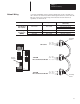

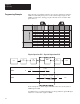
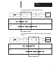
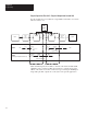
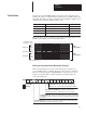
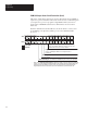
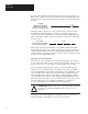
Table Of Contents
- 1747-6.8, Direct Communication Module User Manual
- Important User Information
- Summary of Changes
- Table of Contents
- Preface
- 1 - Overview
- 2 - Quick Start for Experienced Users
- 3 - Addressing
- 4 - Module Configuration
- 5 - Installation and Wiring
- 6 - Programming
- 7 - Troubleshooting
- 8 - Application Examples
- A - Specifications
- B - DCM Addressing Worksheet
- Index
- Back Cover
Chapter 5
Installation and Wiring
5–3
A 1/2 watt terminating resistor must be attached across line 1 and line 2 of
the connectors at each end (scanner and last physical device) of the network.
The size of the resistor depends upon the baud rate and extended node
capability, as shown below:
Baud Rate Terminating Resistor Size
Maximum Cable Distance
(Belden 9463)
Using Extended
Node Capability
All Baud Rates
82W 1/2 Watt
10,000 feet at 57.6K baud
5,000 feet at 115.2K baud
2,500 feet at 230.4K baud
N
ot
Us
i
n
g
57.6K baud
150W 1/2 Watt
3048 meters (10,000 feet)
N
ot
Us
i
n
g
Extended Node
apab l t
115.2K baud
150W 1/2 Watt
1524 meters (5,000 feet)
xten e o e
Capability
230.4K baud
82W 1/2 Watt
762 meters (2,500 feet)
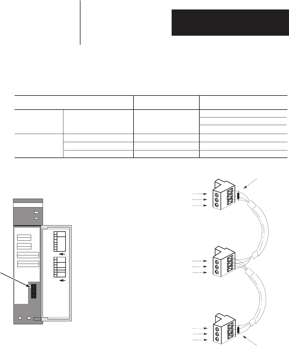
Terminating
Resistor
Terminating
Resistor
RIO
Scanner
1747-DCM
Direct Communication Module
1747-DCM
Direct Communication Module
Line 1 – Blue
Shield – Shield
Line 2 – Clear
Line 1 – Blue
Shield – Shield
Line 2 – Clear
Line 1 – Blue
Shield – Shield
Line 2 – Clear
DCM
RIO Link
Connector
COMM
FAULT
CONFIGURATION
RACK SIZE
1/4 1/2 3/4 1
RACK ADDR
FIRST I/O GROUP
0 2 4 6
DATA RATE (K B/S)
57.6 115.2 230.4
LINE 1 _______
SHIELD ______
LINE 2 _______
1747–DCM
SW2
SW1
O
N
1
2345678
O
N
1
2345678
I/O
GROUP
(LSB)
RACK
ADDRESS
(MSB)
RACK
SIZE
DATA
RATE
X
X
LAST
RACK
CLR ON FL
T
N
et
w
or
k
W
i
r
i
n
g