
User Manual
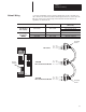

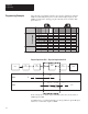
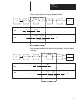
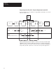
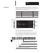
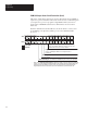
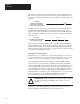
Table Of Contents
- 1747-6.8, Direct Communication Module User Manual
- Important User Information
- Summary of Changes
- Table of Contents
- Preface
- 1 - Overview
- 2 - Quick Start for Experienced Users
- 3 - Addressing
- 4 - Module Configuration
- 5 - Installation and Wiring
- 6 - Programming
- 7 - Troubleshooting
- 8 - Application Examples
- A - Specifications
- B - DCM Addressing Worksheet
- Index
- Back Cover
Chapter 6
Programming
6–2
The following programming examples are typical of applications using the
DCM. In each example the portion of the scanner image assigned to the
DCM is logical rack 2, starting group 0, 1 full rack, and is located in SLC
physical slot 3.
DCM 1
Input
Output
SLC Processor
Power Supply
Physical Slot #
0123456
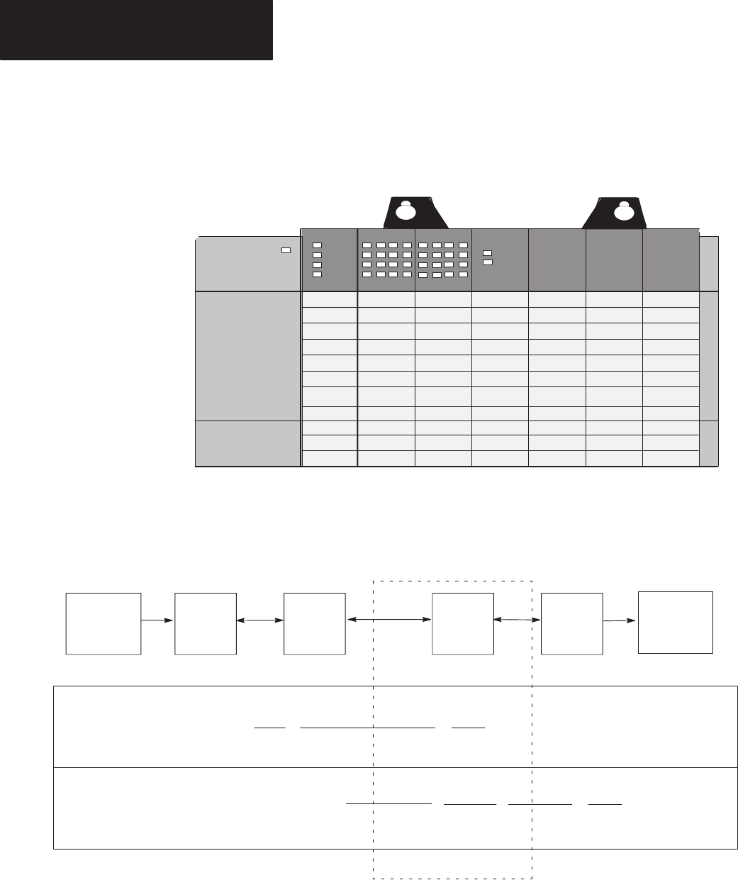
Physical Input into PLC – Physical Output from SLC
] [
I:000
00
( )
O:021
00
] [
I:3.1
00
]/[
I:3.0
08
( )
O:1.0
00
PLC
SLC
PLC
Processor
RIO
Scanner
DCM
SLC
Processor
RIO
Input Output
IN
OUT
Logical Or Status Bit
In the example above, PLC output O:021/00 controls the (on/off) status of
DCM input I:3.1/00.
I:3.1/00 is used as a conditional ladder logic along with the Logical OR input
status bit to control SLC output O:1.0/00.
Programming Examples