
User Manual

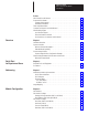

Table Of Contents
- 1747-6.8, Direct Communication Module User Manual
- Important User Information
- Summary of Changes
- Table of Contents
- Preface
- 1 - Overview
- 2 - Quick Start for Experienced Users
- 3 - Addressing
- 4 - Module Configuration
- 5 - Installation and Wiring
- 6 - Programming
- 7 - Troubleshooting
- 8 - Application Examples
- A - Specifications
- B - DCM Addressing Worksheet
- Index
- Back Cover

Direct Communication Module
User Manual
T
able of Contents
i
Preface
Who
Should Use this Manual
P–1. . . . . . . . . . . . . . . . . . . . . . . . . . . . . . . . . . .
Purpose
of this Manual
P–1. . . . . . . . . . . . . . . . . . . . . . . . . . . . . . . . . . . . . . . .
Contents
of this Manual
P–2. . . . . . . . . . . . . . . . . . . . . . . . . . . . . . . . . . . .
Related
Documentation
P–2. . . . . . . . . . . . . . . . . . . . . . . . . . . . . . . . . . . .
Terms
and Abbreviations
P–4. . . . . . . . . . . . . . . . . . . . . . . . . . . . . . . . . . . . . .
Common
Techniques Used in this Manual
P–5. . . . . . . . . . . . . . . . . . . . . . . . . .
Allen-Bradley
Support
P–5. . . . . . . . . . . . . . . . . . . . . . . . . . . . . . . . . . . . . . . .
Local
Product Support
P–5. . . . . . . . . . . . . . . . . . . . . . . . . . . . . . . . . . . . .
Technical Product Assistance P–5. . . . . . . . . . . . . . . . . . . . . . . . . . . . . . . .
Your Questions or Comments on this Manual P–5. . . . . . . . . . . . . . . . . . . . .
Chapter 1
Hardware Overview 1–1. . . . . . . . . . . . . . . . . . . . . . . . . . . . . . . . . . . . . . . . . .
System Overview 1–2. . . . . . . . . . . . . . . . . . . . . . . . . . . . . . . . . . . . . . . . . . .
What
Is a Remote I/O Adapter?
1–2. . . . . . . . . . . . . . . . . . . . . . . . . . . . . .
Extended
Node Capability
1–4. . . . . . . . . . . . . . . . . . . . . . . . . . . . . . . . . .
Scanner Image Division 1–4. . . . . . . . . . . . . . . . . . . . . . . . . . . . . . . . . . . . . . .
Scanner
Image Division Configuration Example
1–5. . . . . . . . . . . . . . . . . . .
Data Exchange Between RIO Scanners and the DCM 1–6. . . . . . . . . . . . . . . . .
What
Is the Status W
ord? 1–6. . . . . . . . . . . . . . . . . . . . . . . . . . . . . . . . . . .
Chapter 2
Required
T
ools and Equipment
2–1. . . . . . . . . . . . . . . . . . . . . . . . . . . . . . . . . .
Procedures 2–2. . . . . . . . . . . . . . . . . . . . . . . . . . . . . . . . . . . . . . . . . . . . . . . .
Chapter 3
Addressing
Ladder Logic Instructions
3–1. . . . . . . . . . . . . . . . . . . . . . . . . . . . .
PLC/Scanner Addresses 3–2. . . . . . . . . . . . . . . . . . . . . . . . . . . . . . . . . . .
SLC Addresses 3–3. . . . . . . . . . . . . . . . . . . . . . . . . . . . . . . . . . . . . . . . . .
I/O
Image T
ables 3–4. . . . . . . . . . . . . . . . . . . . . . . . . . . . . . . . . . . . . . . . .
PLC to DCM/SLC 3–4. . . . . . . . . . . . . . . . . . . . . . . . . . . . . . . . . . . . . .
DCM/SLC
to PLC
3–4. . . . . . . . . . . . . . . . . . . . . . . . . . . . . . . . . . . . . .
Image
Mapping
3–5. . . . . . . . . . . . . . . . . . . . . . . . . . . . . . . . . . . . . . . . . . . . .
Chapter 4
DIP Switches 4–1. . . . . . . . . . . . . . . . . . . . . . . . . . . . . . . . . . . . . . . . . . . . . . .
DIP
Switch 1 Settings
4–2. . . . . . . . . . . . . . . . . . . . . . . . . . . . . . . . . . . . . . . . .
Starting
I/O Group Number (SW1-7 and SW1-8)
4–2. . . . . . . . . . . . . . . . . . .
Rack
Address (SW1-1 through SW1-6)
4–3. . . . . . . . . . . . . . . . . . . . . . . . .
DIP
Switch 2 Settings
4–6. . . . . . . . . . . . . . . . . . . . . . . . . . . . . . . . . . . . . . . . .
Rack
Size (SW2-5 and SW2-6))
4–6. . . . . . . . . . . . . . . . . . . . . . . . . . . . . .
Last Rack (SW2-4) 4–6. . . . . . . . . . . . . . . . . . . . . . . . . . . . . . . . . . . . . . .
Clear
On Fault (SW2-3)
4–7. . . . . . . . . . . . . . . . . . . . . . . . . . . . . . . . . . . .
Data
Rate (SW2-1 and SW2-2)
4–7. . . . . . . . . . . . . . . . . . . . . . . . . . . . . . .
Overview
Quick Start
for Experienced Users
Addressing
Module Configuration