
User Manual
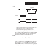
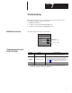
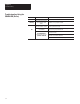


Table Of Contents
- 1747-6.8, Direct Communication Module User Manual
- Important User Information
- Summary of Changes
- Table of Contents
- Preface
- 1 - Overview
- 2 - Quick Start for Experienced Users
- 3 - Addressing
- 4 - Module Configuration
- 5 - Installation and Wiring
- 6 - Programming
- 7 - Troubleshooting
- 8 - Application Examples
- A - Specifications
- B - DCM Addressing Worksheet
- Index
- Back Cover
7
Chapter
7–1
Troubleshooting
This chapter shows you how to identify and correct errors that you may
encounter using LEDs. The topics include:
• DCM status indicators
• troubleshooting using the FAULT LED (red)
• troubleshooting using the COMM LED (green)
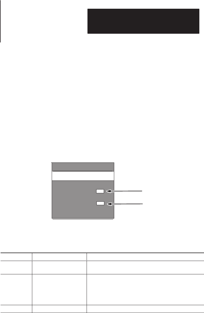
Two LEDs indicate the status of the DCM.
Red
Green
DCM
COMM
FAULT
If LED is: Cause: Corrective action:
On Internal Fault
Cycle power to the I/O chassis containing the DCM.
Replace DCM if red LED remains lit after powerup.
Blinking Configuration Error
Check that the DIP switch settings are correct. Make sure
that I/O group and rack size settings are compatible.
➀
Also see that the setting for rack address is correct. Refer
to chapter 4, Module Configuration, for help with DIP
switches.
Off Normal State No action required.
➀
The
DCM cannot cross logical rack boundaries. Therefore, as an example, configuring the module for 1/2
logical rack with starting group 6 will cause a configuration error
.
DCM Status Indicators
Troubleshooting Using the
FAULT LED (Red)