
User Manual
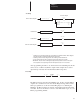

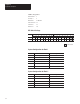
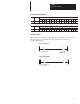


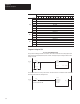
Table Of Contents
- 1747-6.8, Direct Communication Module User Manual
- Important User Information
- Summary of Changes
- Table of Contents
- Preface
- 1 - Overview
- 2 - Quick Start for Experienced Users
- 3 - Addressing
- 4 - Module Configuration
- 5 - Installation and Wiring
- 6 - Programming
- 7 - Troubleshooting
- 8 - Application Examples
- A - Specifications
- B - DCM Addressing Worksheet
- Index
- Back Cover
Chapter 8
Application Examples
8–2
DCM configuration:
Rack Address = 1
I/O Group = 0
Baud Rate = 57.6K baud
Clear On Fault = no
Last Rack = no
Rack Size = 1/4
DIP Switch Settings
Switch 1 Switch 2
1 2 3 4 5 6 7 8 1 2 3 4 5 6 7 8
ON X X X X X X X X X X X X X
OFF X
= Not used
System Configuration for Rack 1
Amount Device Catalog Number
1 Power Supply 1746-P2
1 SLC 5/02 Processor 1747-L524
1 4-Slot Rack 1746-A4
1 AC Input, 16 Inputs 1746-IA16
1 Relay Output, 16 Outputs 1746-OW16
1 Scanner 1747-SN
System Configuration for Rack 2
Amount Device Catalog Number
1 Power Supply 1746-P2
1 SLC 5/01 Processor 1747-L511
1 4-Slot Rack 1746-A4
1 Relay Output, 16 Outputs 1746-OW16
1 DCM 1747-DCM