
User Manual
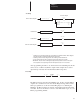

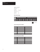
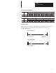


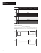
Table Of Contents
- 1747-6.8, Direct Communication Module User Manual
- Important User Information
- Summary of Changes
- Table of Contents
- Preface
- 1 - Overview
- 2 - Quick Start for Experienced Users
- 3 - Addressing
- 4 - Module Configuration
- 5 - Installation and Wiring
- 6 - Programming
- 7 - Troubleshooting
- 8 - Application Examples
- A - Specifications
- B - DCM Addressing Worksheet
- Index
- Back Cover
Chapter 8
Application Examples
8–3
Image Table Configuration
Output Image
15 14 13 12 11 10 9 8 7 6 5 4 3 2 1 0
SN O:3.1/0 0 0 0 0 0 0 0 0 0 0 0 0 0 0 0 1
Input Image
15 14 13 12 11 10 9 8 7 6 5 4 3 2 1 0
DCM I:1.1/0 0 0 0 0 0 0 0 0 0 0 0 0 0 0 0 1
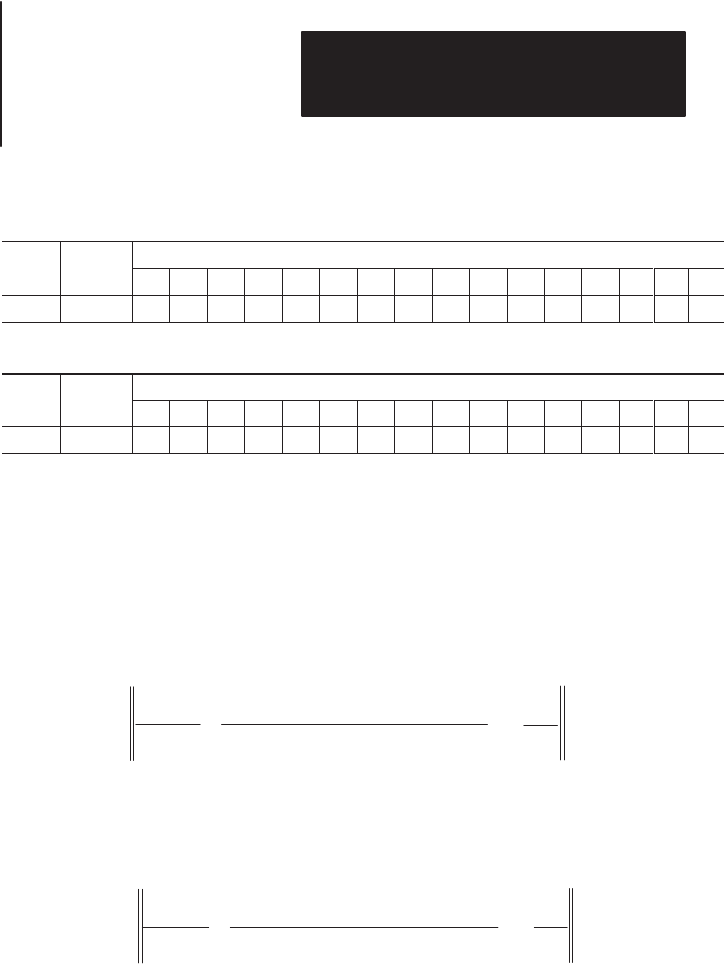
Program Listing
When I:1/0 is set, enabling O:3.1/0 in the SN output image, the data is sent to
the input image of the DCM I:1.1/0. The output in rack 2 is then set to
output module O:2/0.
] [
I:1
0
O:3.1
0
()
From Input Switch To SN Output
Word 1, Bit 0
Rack 1, Program 1
] [
I:1.1
0
O:2
0
()
From DCM Input
Rack 2, Program 2
Word 1, Bit 0