
User Manual
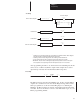
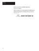
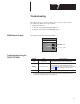

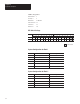
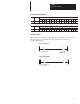


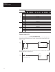
Table Of Contents
- 1747-6.8, Direct Communication Module User Manual
- Important User Information
- Summary of Changes
- Table of Contents
- Preface
- 1 - Overview
- 2 - Quick Start for Experienced Users
- 3 - Addressing
- 4 - Module Configuration
- 5 - Installation and Wiring
- 6 - Programming
- 7 - Troubleshooting
- 8 - Application Examples
- A - Specifications
- B - DCM Addressing Worksheet
- Index
- Back Cover
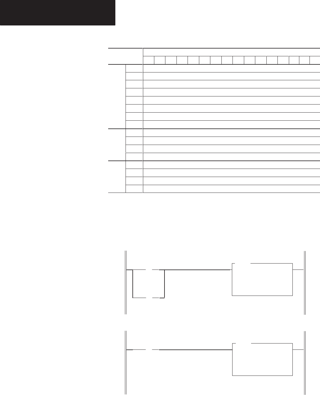
Chapter 8
Application Examples
8–6
Input Image
15 14 13 12 11 10 9 8 7 6 5 4 3 2 1 0
I:1.0 Status Word to SLC from PLC-5
I:1.1 Not used
I:1.2 Not used
I:1.3 Not used
DCM
I:1.4
Not used
I:1.5 Not used
I:1.6 Not used
I:1.7 Not used
I:2.0 NI4 word 0
I:2.1 NI4 word 1
NI4
I:2.2
NI4 word 2
I:2.3 NI4 word 3
I:3.0 NI4 word 0
I:3.1 NI4 word 1
NI4
I:3.2
NI4 word 2
I:3.3 NI4 word 3
Program Listing for 5/01
Processor File: MULTPLX1.ACH
Rung 0 sets the starting point of the C5:0 counter. This is done on the first scan of the program S:1/15
(first scan bit) and C5:0/DN (done bit 0) of the counter, ensuring that only the analog modules in slots 2
through 5 are read.
] [
C5:0
DN
RUNG
2.0
] [
S:1
15
MOV
MOVE
Source 2
Dest C5:0.ACC
Rung 1 increments the C5:0 every 5.12 seconds. The value in the ACC is referenced to the slot that the
DCM will send the data from, starting at slot 2.
] [
S:4
RUNG
2.1
CTU
Countup
Counter C5:0
Preset 6
Accum 0
8
5.12 Seconds Time Bit