
User Manual
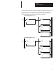
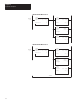


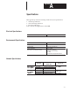
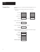


Table Of Contents
- 1747-6.8, Direct Communication Module User Manual
- Important User Information
- Summary of Changes
- Table of Contents
- Preface
- 1 - Overview
- 2 - Quick Start for Experienced Users
- 3 - Addressing
- 4 - Module Configuration
- 5 - Installation and Wiring
- 6 - Programming
- 7 - Troubleshooting
- 8 - Application Examples
- A - Specifications
- B - DCM Addressing Worksheet
- Index
- Back Cover
B
Appendix
B–1
DCM Addressing Worksheet
This appendix provides a worksheet for keeping track of the elements of each
I/O address for your system’s DCMs. Topics include:
• directions
• addressing review
In the table on the next page, enter the elements of each I/O address for each
DCM in your system. All DCM inputs and outputs are addressed with
respect to the SLC.
Make sufficient copies of this worksheet to cover all DCMs in your system.
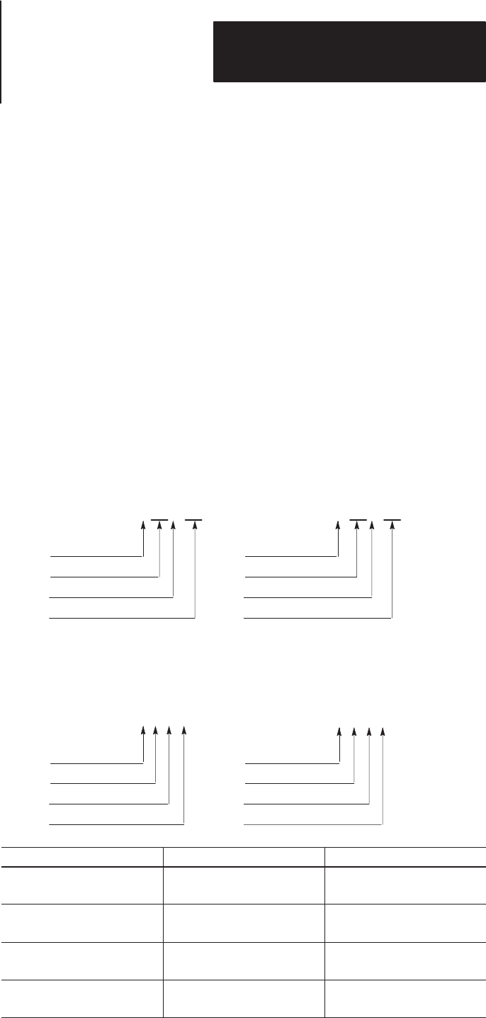
PLC Addresses
I = Input
O:017/10I:023/10
02 = Logical Rack
3 = I/O Group
10 = Bit (octal)
O = Output
01 = Logical Rack
7 = I/O Group
10 = Bit (octal)
PLC Input
Address
PLC Output
Address
SLC Addresses
I = Input
O:1.7/8I:2.3/8
2 = Physical Slot
3 = Word
8 = Bit (decimal)
O = Output
1 = Physical Slot
7 = Word
8 = Bit (decimal)
SLC Input
Address
SLC Output
Address
If you configure the DCM as: Then: Including the Status Word
1/4 Rack
1 data word (16 bits of I/O
data) is transferred.
Total transfer = 2 words
1/2 Rack
3 data words (48 bits of I/O
data) are transferred.
Total transfer = 4 words
3/4 Rack
5 data words (80 bits of I/O
data) are transferred.
Total transfer = 6 words
Full Rack
7 data words (112 bits of I/O
data) are transferred.
Total transfer = 8 words
Directions
Addressing Review