
Owner manual
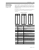
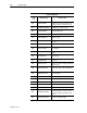
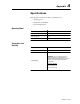
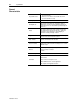
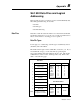
Table Of Contents
- 1747-6.1, Data Table Access Module User Manual
- Important User Information
- Summary of Changes
- Table of Contents
- Preface
- 1 - Data Table Access Module Overview
- 2 - Installation and Power Up
- 3 - Module Setup Procedure
- 4 - Attaching to a Processor
- 5 - Monitoring and Modifying Data
- 6 - Quick Recall Functions
- 7 - Processor Control Functions
- 8 - Message Capability
- 9 - Troubleshooting
- A - Specifications
- B - SLC 500 Data Files and Logical Addressing
- C - Module Display Character Set
- D - Mounting Template
- Index
- Back Cover
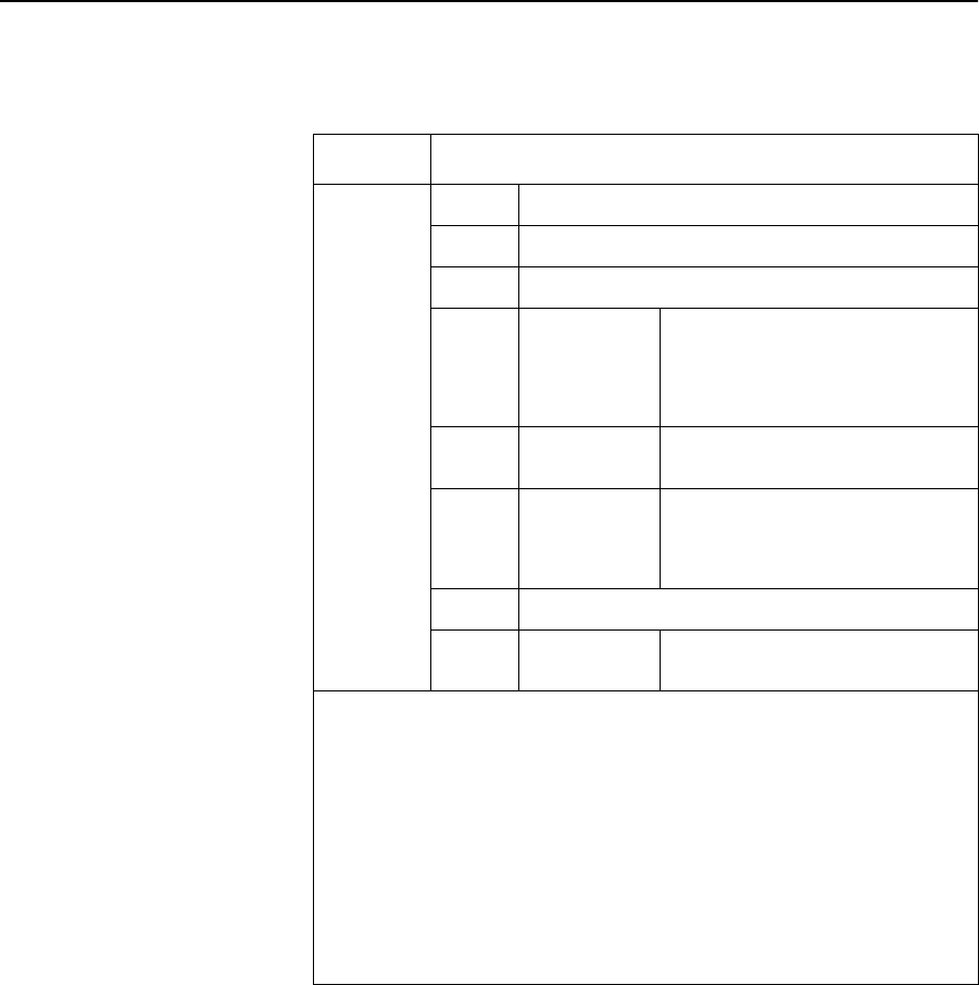
B-4 SLC 500 Data Files and Logical Addressing
Publication 1747-6.1
I/O addresses are assigned to modular controllers as shown in the
table below:
Format Explanation
O:e.s/b
I:e.s/b
O Output
I Input
: Element delimiter
e
Slot number
(decimal)
Slot 0, adjacent to the power supply in
the first rack, applies to the processor
module (CPU). Succeeding slots are I/O
slots, numbered from 1 to a maximum of
30.
. Word delimiter.
Required only if a word number is
necessary as noted below.
s Word number
Required if the number of inputs or
outputs exceeds 16 for the slot. Range:
0-255 (range accomodates multi-word
specialty I/O modules).
/ Bit delimiter
b
Terminal
number
Inputs: 0 to 15
Outputs:0to15
Examples:
O:3/15
O:5/0
O:10/11
I:7/8
I:2.1/3
Output 15, slot 3
Output 0, slot 5
Output 11, slot 10
Input 8, slot 7
Input 3, slot 2, word 1
Word
Addresses
O:5
O:5.1
I:8
Output word 0, slot 5
Input word 1, slot 5
Input word 0, slot 8