
Owner manual
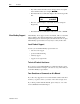
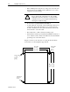
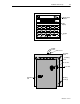
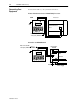
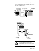
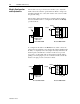
Table Of Contents
- 1747-6.1, Data Table Access Module User Manual
- Important User Information
- Summary of Changes
- Table of Contents
- Preface
- 1 - Data Table Access Module Overview
- 2 - Installation and Power Up
- 3 - Module Setup Procedure
- 4 - Attaching to a Processor
- 5 - Monitoring and Modifying Data
- 6 - Quick Recall Functions
- 7 - Processor Control Functions
- 8 - Message Capability
- 9 - Troubleshooting
- A - Specifications
- B - SLC 500 Data Files and Logical Addressing
- C - Module Display Character Set
- D - Mounting Template
- Index
- Back Cover
Installation and Power Up 2-5
Publication 1747-6.1
You can connect the DTAM module to an SLC 5/04 or later processor
using either of the following methods.
Connection to a DH485 Network Using an Interface Module
Connection to a DH485 Network Using Link Couplers
DTAM
CH
Interconnect Cable
1.8 m (6 ft.) 1747-C10
SLC 5/04 Processor
(1747-L542)
Interface Module
(1747-KE)
9-pinto9-pin
Connector
(1747-CP3)
DTAM
CH
Interconnect Cable
1.8 m (6 ft.) 1747-C10
Advanced Interface Coupler
1761-NET-AIC
Link Coupler
1747-AIC
Communications
Cable
Belden 9842
Earth Ground
To 24V dc
Power Supply
1747-CP3
To SLC 5/04 Processor
To 24V dc
Power Supply
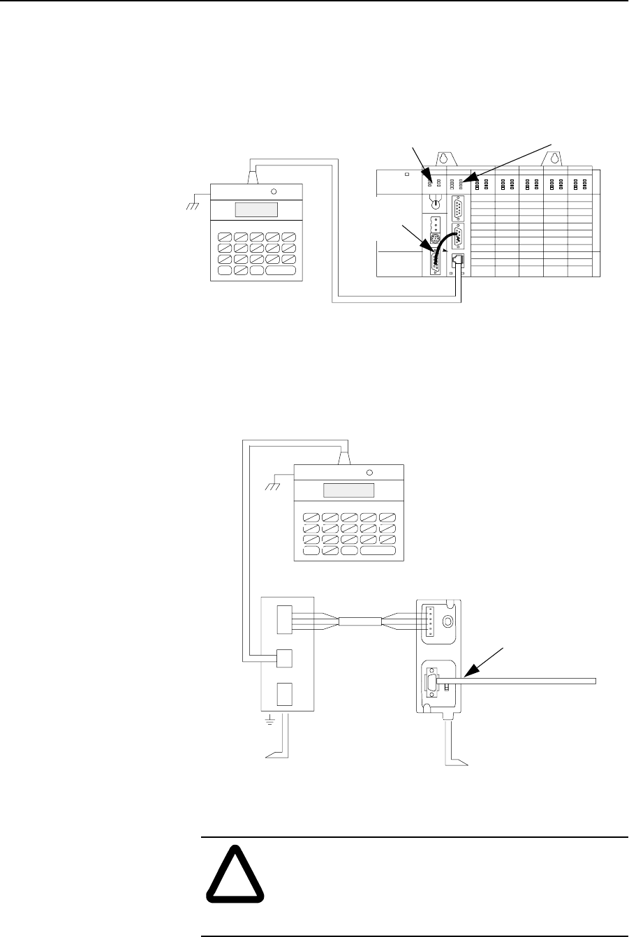
!
ATTENTION: The DTAM module end of the
interconnect cable has pins that carry 24V dc.
Disconnect the cable at the processor or link coupler to
guard against connector short circuits and possible
damage to the processor.