
Owner manual
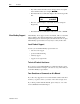
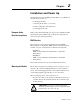
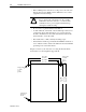
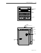
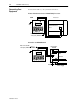
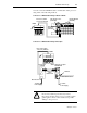
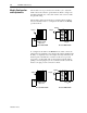
Table Of Contents
- 1747-6.1, Data Table Access Module User Manual
- Important User Information
- Summary of Changes
- Table of Contents
- Preface
- 1 - Data Table Access Module Overview
- 2 - Installation and Power Up
- 3 - Module Setup Procedure
- 4 - Attaching to a Processor
- 5 - Monitoring and Modifying Data
- 6 - Quick Recall Functions
- 7 - Processor Control Functions
- 8 - Message Capability
- 9 - Troubleshooting
- A - Specifications
- B - SLC 500 Data Files and Logical Addressing
- C - Module Display Character Set
- D - Mounting Template
- Index
- Back Cover
2-6 Installation and Power Up
Publication 1747-6.1
Module Configuration
and Adjustments
The module’s access port and access hole allow you to adjust the
LCD contrast and select the operational mode. Refer to chapter 5 to
determine which mode to select, then return to this section to make
the physical setting.
The module is shipped from the factory with the jumper installed
between terminals 1 and 2 to configure the module for the Modify
operational mode.
To configure the module for the Monitor mode, either connect the
jumper between terminals 1 and 3 (leaving the jumper installed in the
module) or completely remove the jumper. You may either leave the
header in place and make the connection via the access port and
access hole, or temporarily remove the header from the module by
pulling it off of the plug. If you choose the latter method, return the
header to the plug once the connection is made.
3
2
1
Jumper
Header
Plug
LCD Contrast
Adjust Pot
Jumper
Access Hole View
Access Port View
3
2
1
Jumper
Header
Plug
LCD Contrast
Adjust Pot
Jumper
Access Hole View
Access Port View