
Owner manual
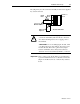
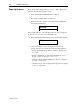
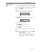
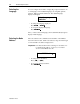
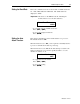
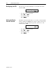
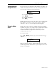

Table Of Contents
- 1747-6.1, Data Table Access Module User Manual
- Important User Information
- Summary of Changes
- Table of Contents
- Preface
- 1 - Data Table Access Module Overview
- 2 - Installation and Power Up
- 3 - Module Setup Procedure
- 4 - Attaching to a Processor
- 5 - Monitoring and Modifying Data
- 6 - Quick Recall Functions
- 7 - Processor Control Functions
- 8 - Message Capability
- 9 - Troubleshooting
- A - Specifications
- B - SLC 500 Data Files and Logical Addressing
- C - Module Display Character Set
- D - Mounting Template
- Index
- Back Cover
Installation and Power Up 2-7
Publication 1747-6.1
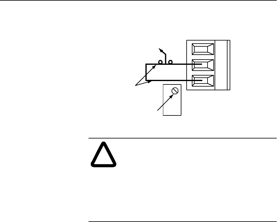
The jumper may be removed and an externally mounted user-supplied
key switch connected.
Modify
Mode
Monitor
Mode
Terminal 3 is
unused.
LCD Contrast
Adjust Pot
1.83 m (6 ft.)
Maximum distance
Access Port View
!
ATTENTION: To avoid damaging the module, when
you wire an external keyswitch for mode control, use
an isolated switching device. Do not apply power to
the terminals.
ATTENTION: To avoid damaging the module, when
you change the mode select jumper, disconnect power
from the module. Move the top lead of the jumper
between terminals 2 and 3. Always leave the lead
attached to the bottom terminal (terminal 1) connected.
Important: After you have set up the module for your application,
to prevent unauthorized access to data files, connect the
jumper for the Monitor mode or wire the key switch as
shown .