
Owner manual
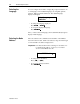
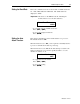

Table Of Contents
- 1747-6.1, Data Table Access Module User Manual
- Important User Information
- Summary of Changes
- Table of Contents
- Preface
- 1 - Data Table Access Module Overview
- 2 - Installation and Power Up
- 3 - Module Setup Procedure
- 4 - Attaching to a Processor
- 5 - Monitoring and Modifying Data
- 6 - Quick Recall Functions
- 7 - Processor Control Functions
- 8 - Message Capability
- 9 - Troubleshooting
- A - Specifications
- B - SLC 500 Data Files and Logical Addressing
- C - Module Display Character Set
- D - Mounting Template
- Index
- Back Cover
2-8 Installation and Power Up
Publication 1747-6.1
Power-Up Sequence
When the module is plugged into a processor or link coupler for the
first time, the following sequence occurs:
1. The Communications LED illuminates solid red.
2. The module performs diagnostic self tests.
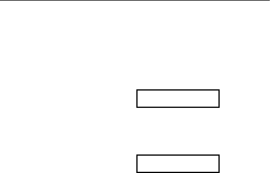
3. When the tests are complete, the Communications LED turns
off, and the LCD displays:
If the module fails any of the self diagnostic tests, refer to chapter 9,
Troubleshooting, for a list of error and fault codes.
4. The Communications LED flashes green, and the LCD displays:
5. After a successful power-up, the display shows the ready
prompt. You can now perform any of the following functions:
• Change the Module Setup. Refer to chapter 3, Module Setup
Procedure.
• Initiate communications with a SLC 500 family processor.
Refer to chapter 4, Attaching to a Processor.
• Clear an existing Quick Recall Function. Refer to chapter 6,
Quick Recall Functions.
• Observe and respond to a displayed message. Refer to chapter
8, Message Capability.
Enter Network
Working...
RDY>