
Owner manual
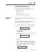
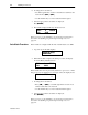
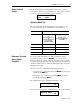
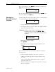
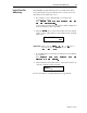
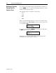
Table Of Contents
- 1747-6.1, Data Table Access Module User Manual
- Important User Information
- Summary of Changes
- Table of Contents
- Preface
- 1 - Data Table Access Module Overview
- 2 - Installation and Power Up
- 3 - Module Setup Procedure
- 4 - Attaching to a Processor
- 5 - Monitoring and Modifying Data
- 6 - Quick Recall Functions
- 7 - Processor Control Functions
- 8 - Message Capability
- 9 - Troubleshooting
- A - Specifications
- B - SLC 500 Data Files and Logical Addressing
- C - Module Display Character Set
- D - Mounting Template
- Index
- Back Cover
4-2 Attaching to a Processor
Publication 1747-6.1
6. To change the node address:
• Scroll through the list of active node addresses attached to the
network. Press [
]or[ ].
• Use the numeric keys to enter a value from 0 through 31.
7. Once the appropriate node address is displayed:
Press [
].
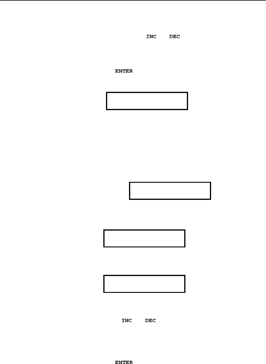
8. The module displays the Ready Attached screen:
If the processor you are attaching to is password-protected, refer to
the section on attaching to a password-protected processor on
page 4-4.
Auto Attach Procedure
If the module is configured with the Auto Attach feature set to On:
1. At power up, the module displays:
2. When the module completes the attach procedure, the display
shows the Ready Attached screen:
If the module has not been previously attached to a processor or if the
last processor it was attached to is no longer active, the display shows:
1. To change the node address:
•Press[
]or[ ] to scroll through the list of active node
addresses attached to the network.
• Use the numeric keys to enter a value from 0 through 31.
2. Once the appropriate node address is displayed:
Press [
].
If the processor you are attaching to is password-protected, refer to
the section on attaching to a password-protected processor on
page 4-4.
RDY> 4 RRUN
5/02 4444
Attach to CPU?
WORKING . . . .
RDY> 4 RRUN
5/02 4444
Attach to CPU?
**